AM1 · PUBLIC EDITION · 6 OCTOBER 2026
Build from the parts you have
Count your actual prints, find your next cold-fit check, and keep your place. The illustrated AM1 manual stays below for every joint and hold point.
YOUR BENCH
What have you printed?
Count cooled, undamaged, correctly identified full-size parts. Nothing is assumed printed. A count unlocks a check, not approval to assemble or apply load.
Saved only in this browser. No account sync. Public visitors cannot see your checklist.
Clear all counts and fit checks saved in this browser?
Three of four specified M2 nut-loading routes in C01 are obstructed. No revised carrier or alternative route is verified. Step 07 inspection and Step 08 dry travel are separate checks.
The nominal stack is 38 mm before the nut or washers. The identified kit stops at 30 mm. Longer hardware still needs a measured stack and safe-tip check.
What should I buy next?
Only missing parts: 1 reSpeaker Lite USB board (107990273), 1 matched Seeed speaker (114993346), and 1 USB-A–USB-C data cable. Reuse a suitable cable and measuring tools. Camera comes later; motors and battery parts are not part of this stationary build.
See the prioritized parts listPublic AM1 preserves the technical instructions and hold points. Personal purchase records, private source links and individual print-status history are omitted.
Contents · parts, 17 steps and joint records
Before you begin
Mechanical fit edition AM1 | Public edition | 6 October 2026
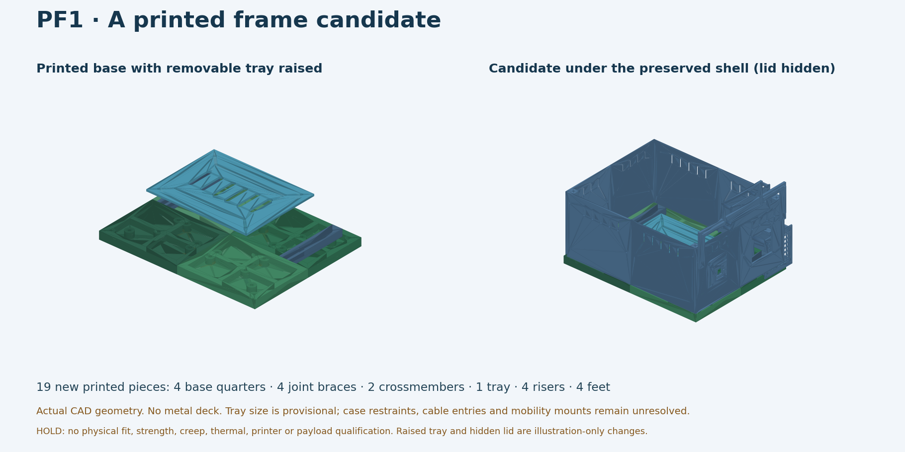
Actual CAD illustration of the current printed-frame candidate. The internal tray is raised for visibility; this is not a photograph or a load-qualified assembly.
Follow the numbered steps to identify the parts, understand every joint and make the cold, unloaded checks in a controlled order. Screw callouts identify the thread, location and required stack; a length is only usable when the actual nut, washer and tip-clearance checks pass.
No power, battery connection, motor operation, heating test, lifting by the microphone bridge or payload test is part of this manual.
Back to contents ↑How to use this manual
Start with Steps 01–03. If the parts needed for a later step are absent, mark that step pending and keep its parts together. A printer completing a job does not establish dimensional fit.
| Section | What you will do |
|---|---|
| Parts and hardware | Identify 24 shell pieces, 13 front-module pieces and 19 frame pieces. Match the eight catalog screw lengths to actual joint requirements. |
| Steps 01–06 · body | Check hardware; orient handed posts; fit one corner, seams, walls and the removable lid. |
| Steps 07–09 · camera | Inspect the blocked nut paths, dry-check the shutter, and prepare the conditional camera mounting stack. |
| Steps 10–13 · speaker and microphone | Check ear recesses, long grille bolts, actual microphone-board revision, bridge and service access. |
| Steps 14–17 · unfinished frame | Check the small seam sample first. The full base, feet/crossmembers, tray and body-to-base joints follow only after their fit gates. |
| Joint records and sources | Record measured stacks and fit outcomes. Source-derived dimensions are design values, not physical measurements. |
Three different kinds of evidence
• CAD geometry: shapes, hole axes and nominal stack distances taken from the existing models. It does not prove the printed part or hardware fits.
• Catalog stock: sizes and counts shown for the identified Amazon ASIN. Verify the actual package before relying on the catalog stock.
• Accepted physical fit: a specific inspected print, with the actual screw and nut, seated without force and with safe tip clearance. Record this separately.
Assembly conditions
• Work on a flat, clear table with the parts fully cooled and all electronics disconnected.
• Use hand tools. Do not use a power driver, pull a gap closed with a screw, cut new holes, heat-set unapproved inserts or glue the service joints.
• Stop for a crack, white stress mark, nut spinning in its pocket, unsupported screw head, blocked tool access or a screw tip touching another part.
• No tightening torque is qualified. This edition supports fit checks and light, reversible hand assembly only.
Back to contents ↑Parts checklist · 24-piece shell
The labels below are file/geometry identifiers. The physical prints may be unmarked. Use dimensions, holes, vents and handed nut access to identify them; never identify a post only by how it lies on the table.
| Part ID / appearance | Qty | Nominal bounds, mm | Physical check |
|---|---|---|---|
| R2_side · vented long-wall half | 4 | 135 × 120 × 3 | Inspect and count actual parts |
| R2_end · plain rear-wall half | 2 | 108 × 120 × 3 | Inspect and count actual parts |
| R2_front_module_panel · square opening | 2 | 108 × 120 × 3 | Inspect and count actual parts |
| R2_lid · flat roof quarter | 4 | 138 × 108 × 3 | Inspect and count actual parts |
| R2_post_pp · front / +Y | 1 | 12 × 12 × 120 | Inspect and count actual parts |
| R2_post_pn · front / −Y | 1 | 12 × 12 × 120 | Inspect and count actual parts |
| R2_post_np · rear / +Y | 1 | 12 × 12 × 120 | Inspect and count actual parts |
| R2_post_nn · rear / −Y | 1 | 12 × 12 × 120 | Inspect and count actual parts |
| R2_joiner · two holes and two hex pockets | 8 | 36 × 18 × 6 | Count only full-size accepted joiners |
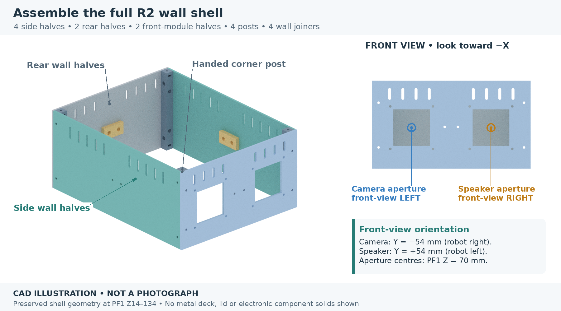
Current R2 wall and post geometry. The four-tile lid is assembled separately in Step 06; front accessories and PF1 frame have their own steps.
Physical count found: ______ | Accepted for this cold-fit mockup: ______ | Missing or damaged IDs: __________________
Back to contents ↑Parts checklist · 13 front pieces
| Part ID | Qty | What to recognize | Physical check |
|---|---|---|---|
| C01 camera carrier | 1 | 72 × 66 × 5; optical window, rails and nut pockets | Inspect and count actual parts |
| C02 shutter retainer | 1 | 62 × 48 × 1.6; centre window and finger slot | Inspect and count actual parts |
| C03 slider | 1 | 22 × 27.5 × 5.9; solid blade and raised grip | Inspect and count actual parts |
| C04 camera spacer | 4 | 4.2 mm OD × 6 mm long; M2 passage | Inspect and count actual parts |
| S01 speaker cassette | 1 | 66 × 67.5 × 33; ear supports and four tall columns | Inspect and count actual parts |
| S02 speaker grille | 1 | 66 × 72 × 2; lattice with four mounting holes | Inspect and count actual parts |
| M01 microphone U-bridge | 1 | 210 × 96 × 18; wide bridge and asymmetric board supports | Inspect and count actual parts |
| M02 microphone guard | 1 | 96 × 46 × 2; microphone, button and indicator openings | Inspect and count actual parts |
| M03 bridge spacer | 2 | 8 mm OD × 2 mm long; M3 passage | Inspect and count actual parts |
Separate the test pieces
T01 is a short camera-guide test section, not a replacement C01. T02 is one speaker-ear support test section, not a replacement S01. The tolerance coupon, shortened post, panel-corner pieces and aperture sample are inspection aids. Keep them in a separate bag.
Inspect the actual printed pieces
A completed print job, a cleared bed or a file in a slicer does not prove that every required piece is present, usable or dimensionally correct. Identify and inspect the actual parts before checking any assembly quantity off.
Specified front-module interfaces
Candidate interfaces use Camera Module 3 Standard, Seeed speaker 114993346 and USB-only reSpeaker Lite 107990273. Substitute hardware is not automatically compatible. Component presence, received revision and fit are separate checks; no electronics need to be powered for the steps in this edition.
Back to contents ↑Parts checklist · unfinished PF1 frame
| Part ID | Qty | Role / nominal dimensions | Count found |
|---|---|---|---|
| F01 front-left base | 1 | Ribbed quarter; 139.8 × 109.8 × 14 mm | ____ |
| F02 front-right base | 1 | Different handed quarter; same overall bounds | ____ |
| F03 rear-left base | 1 | Different handed quarter; same overall bounds | ____ |
| F04 rear-right base | 1 | Different handed quarter; same overall bounds | ____ |
| F05 under-seam splice | 4 | Underside overlapping joint; four M4 axes | ____ |
| F06 crossmember | 2 | Front/rear; 190 × 18 × 12 mm | ____ |
| F07 equipment tray | 1 | 180 × 140 mm envelope; slotted floor | ____ |
| F08 tray riser | 4 | 14 mm height | ____ |
| F09 stationary foot | 4 | 8 mm height; underside nut pocket | ____ |
Actual CAD frame layout. These 19 installed pieces are additional to the 37-piece body. Qualification and usable physical inventory remain open.
Small joint specimens: FT01 + FT02 on P12, plus one extra F05 on P13. Inspect each physical specimen; filenames and job records do not establish completion or fit. These specimens do not automatically reduce the 19-piece installed inventory.
Back to contents ↑Reference M3 kit · eight lengths
Catalog: VGBUY 600-piece socket-cap assortment, ASIN B0D1XJ766V, M3 × 0.5 thread. The listing specifies 20 screws each in 6/8/10/12/16/20 mm, 15 each in 25/30 mm, and 150 each of plain hex nuts, flat washers and split lock washers. [S4]
![Seller’s catalog image for the identified ASIN, showing screw lengths measured under the socket-cap head. This is a product reference, not a photograph of any particular received package. [S4]](../assets/assembly-am1/image3.jpg)
Seller’s catalog image for the identified ASIN, showing screw lengths measured under the socket-cap head. This is a product reference, not a photograph of any particular received package. [S4]
Back to contents ↑01 Read the screw size before using it
Check the listed parts and fit requirements before starting.
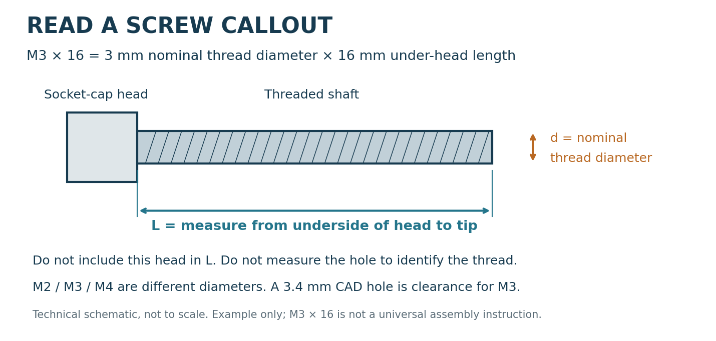
Technical measurement diagram; the example length is not a released universal screw size.
PARTS Reference M3 kit or verified equivalent, one loose test screw and matching nut; tolerance coupon if available.
TOOLS Millimetre ruler or calipers; hand hex keys; small tray for loose nuts.
FASTENERS M3 × L socket-cap, where L is the measured under-head length. Do not choose a length from head size.
1. Sort by the box labels. Check one screw from each compartment with the ruler or calipers; measure from the underside of the head to the tip.
2. Start a matching loose nut on the screw by fingers, away from the robot. It should run freely without being forced. A socket driver must fit the head securely; the exact included key size is not confirmed here.
3. Measure the actual nut across its flats and its thickness. Measure any proposed flat washer’s outside diameter and thickness. Keep split lock washers separate; they are not automatically part of every plastic joint.
4. Use the joint-specific callout in the next steps. A screw must reach through the nut’s full threaded thickness without a harmful tip projection or bottoming out.
Back to contents ↑02 Orient the four handed posts
Check the listed parts and fit requirements before starting.
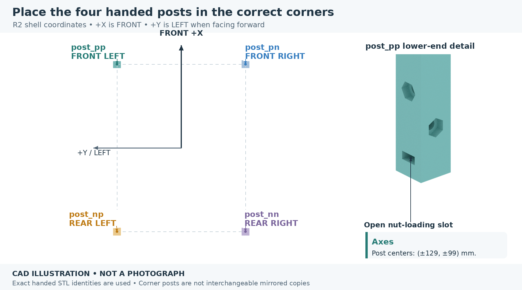
Actual post geometry with the current front and handed coordinates identified. Nut-access faces point inward.
PARTS R2_post_pp, pn, np and nn, one of each.
TOOLS Paper labels, ruler and a flat table.
FASTENERS None for this identification step. Each completed post ultimately has side/end M3 fasteners plus one top and one bottom M3 attachment.
1. Mark the robot’s front as +X. Looking down with front at the top of the diagram, match each post to pp (+X,+Y), pn (+X,−Y), np (−X,+Y) and nn (−X,−Y).
2. Find the open inward nut-access features. The two external panel faces must face the matching outer walls; do not rotate a wrong-handed post until it merely looks close.
3. The side-wall screw levels are 17 and 102 mm above the post bottom. The front/rear panel levels are 29 and 90 mm above the post bottom. Their different heights identify the two faces.
4. While the post is accessible, test the actual M3 nut in each upper and lower inward side slot. These are 9.6 × 6 × 2.8 mm rectangular openings, not hex recesses. It must enter and come out without force.
5. Label each post on removable tape. Keep any shortened test post separate. Remove unsupported nuts after the fit check, and install/support them when their top or bottom screws are fitted.
Back to contents ↑03 Dry-fit one side and one end
Check the listed parts and fit requirements before starting.
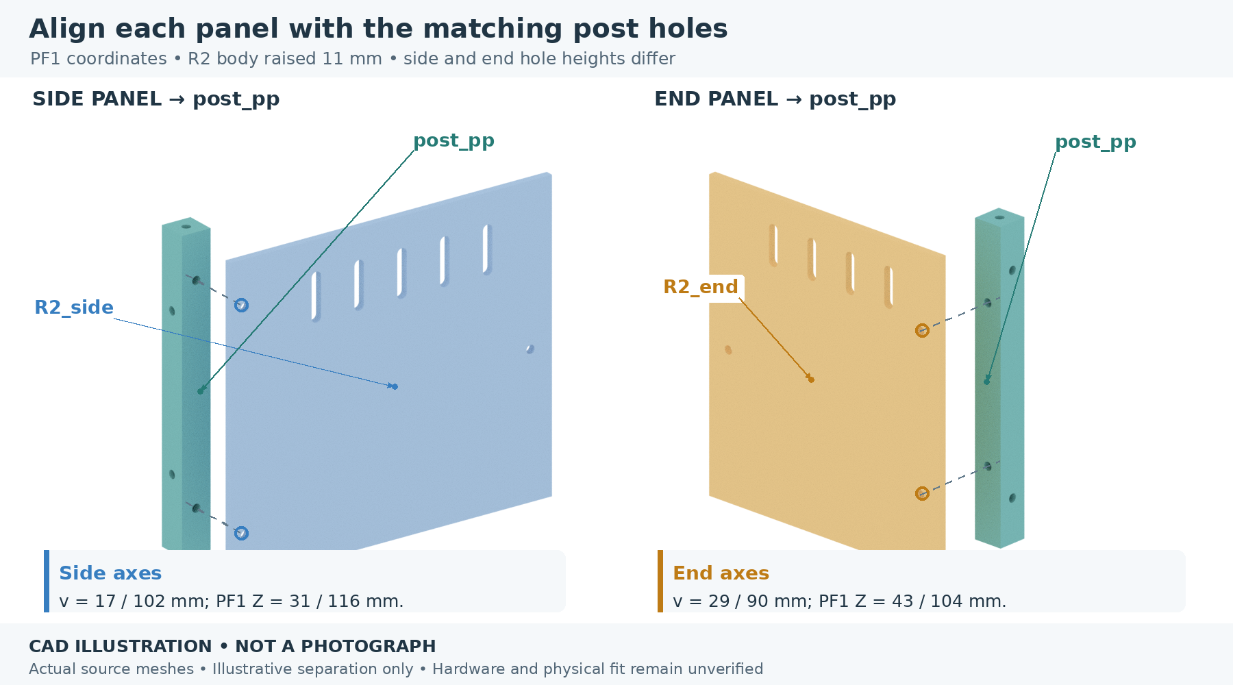
Actual panel/post interfaces. Screw axes are shown; fastener shape and final lengths remain subject to the stack check.
PARTS One full R2_side, one matching front or rear half, and the correctly handed post.
TOOLS Flat support, ruler, calipers and hand hex key.
FASTENERS Four M3 positions at this corner. M3 × 16 socket-cap is the first catalog comparison for ordinary wall/post joints (H01); final fit depends on the actual nut, washers and tip clearance.
1. Keep the post upright and support it. Put the 3 mm side panel against its outside face with vents high. Align the two side holes at post-local heights 17/102 mm.
2. Offer the front/rear panel to the other outside face. Its two post holes are at local heights 29/90 mm. Do not swap these with the side-panel heights.
3. Check the inward-facing M3 hex pockets without driving a nut into them. R2 nominal pocket width is 5.7 mm across flats; the side-pocket actual recessed depth is 2.7 mm.
4. With a compatible nut seated and visible, compare the actual screw length against the joint stack. Insert by hand only after the path, head support and tip clearance have been checked. Leave the fit loose.
Back to contents ↑04 Fit the inside wall joiners
Check the listed parts and fit requirements before starting.
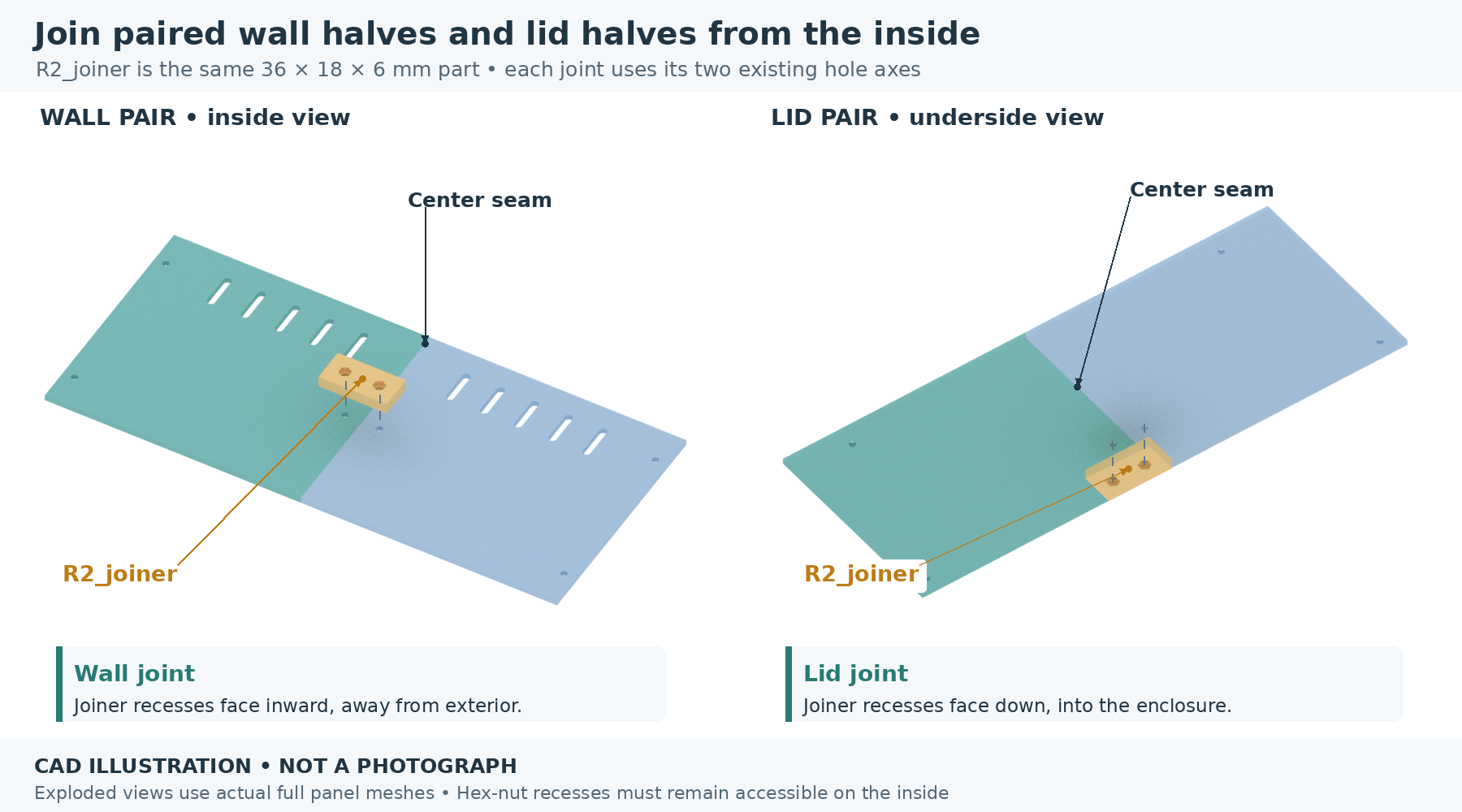
Actual joiners bridge the inside of panel seams. The hex-pocket side faces the interior, where the nuts can be supported.
PARTS Four R2_joiners for walls; paired side, front and rear halves as available.
TOOLS Flat table, hand hex key, small nut holder and calipers.
FASTENERS Eight M3 positions, two per joiner. Compare M3 × 10 socket-cap (H03): the CAD seat span is 6.3 mm before the nut and washers; safe projection still needs checking.
1. Place two matching panel halves edge-to-edge on the table. Their exterior surfaces are aligned; each seam hole lies 9 mm from the mating edge.
2. Put one joiner across the inside of the seam. Its hole centres are 18 mm apart, matching the two panel seam holes. The flat joiner face meets the panels; hex recesses face inward.
3. Seat the two measured M3 nuts gently in the accessible recesses. Compare each screw’s under-head length with 6.3 mm plus washer thickness plus the actual nut thickness; also inspect where the tip will end.
4. Start both screws by fingers, keep the seam straight and only remove looseness after the two surfaces lie naturally flat. Repeat for the other three wall seams as parts become available.
Back to contents ↑05 Complete the body walls loosely
Check the listed parts and fit requirements before starting.
CAD REFERENCE · Use for geometry and hardware
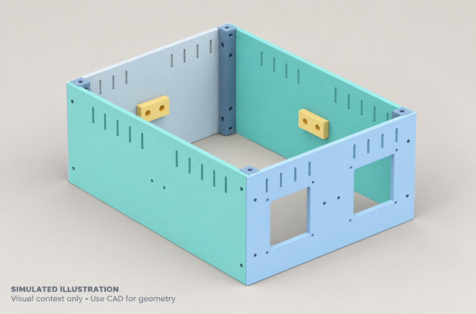
Actual R2 wall and post assembly, with front module openings identified. Front is +X; camera is front-view left and speaker front-view right.
PARTS Four handed posts; four side halves; two rear halves; two front-module halves; four wall joiners.
TOOLS Flat table, temporary supports, hand hex key and ruler.
FASTENERS 16 post-side/end M3 positions plus 8 wall-seam M3 positions. The microphone bridge later replaces two upper-front screw stacks, not two additional holes.
1. Extend the accepted single-corner fit around the body. Keep all vents high and all nut pockets facing the service interior.
2. Use the two panels with 50 × 50 mm apertures at the front. Use the two plain end panels at the back. Each front opening has four M3 module holes on a 58 × 58 mm square.
3. Fit each inside wall joiner. Keep fasteners loose until all corners and seams agree. Support the walls independently while the PF1 frame is unfinished.
4. Check the front view: the camera belongs on the viewer’s left and speaker on the viewer’s right. Label the two openings before fitting modules.
Back to contents ↑06 Build the removable service lid
Check the listed parts and fit requirements before starting.
CAD REFERENCE · Use for geometry and hardware
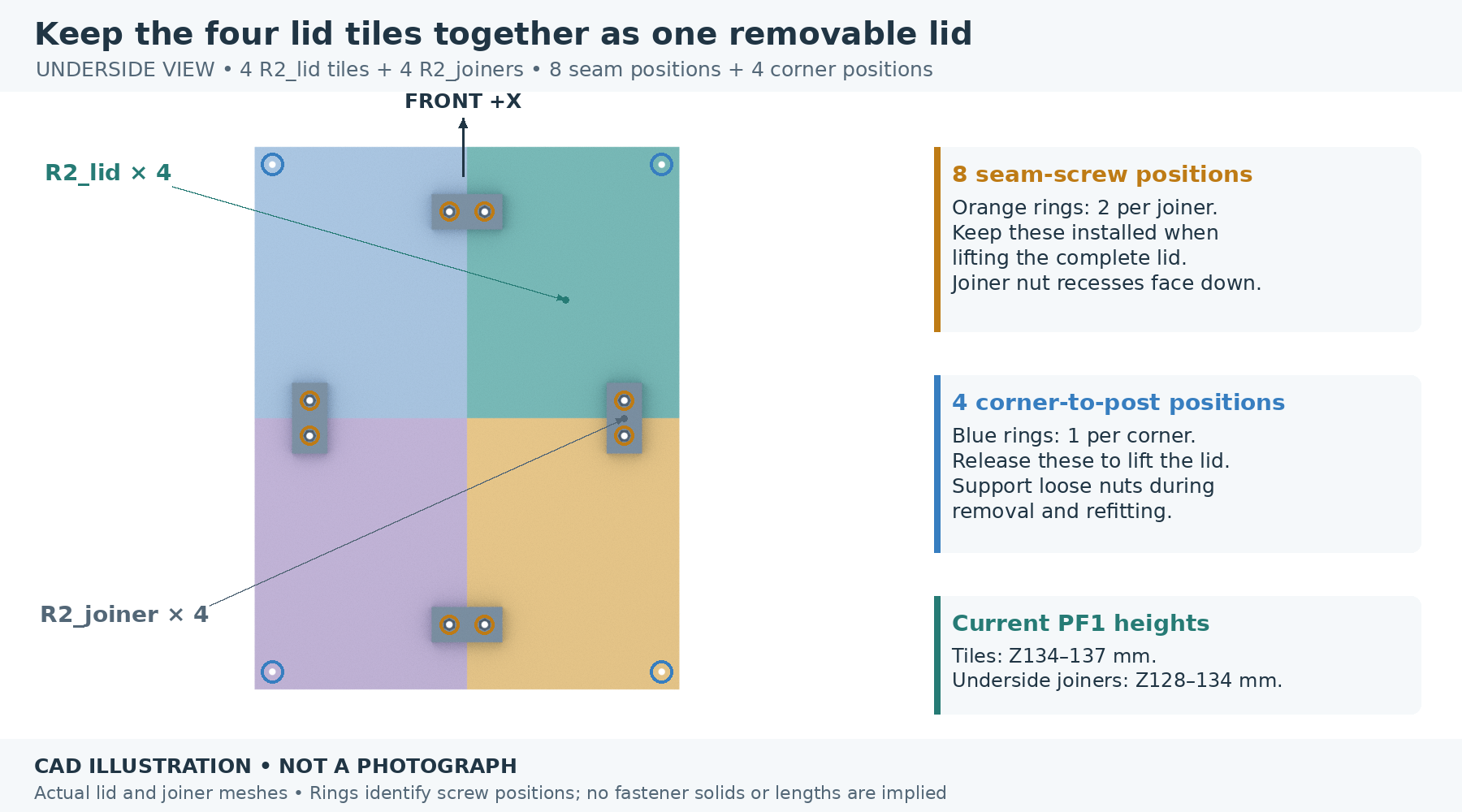
Actual four-tile lid underside. Four joiners carry eight seam positions; four separate corner holes secure the lid to the posts.
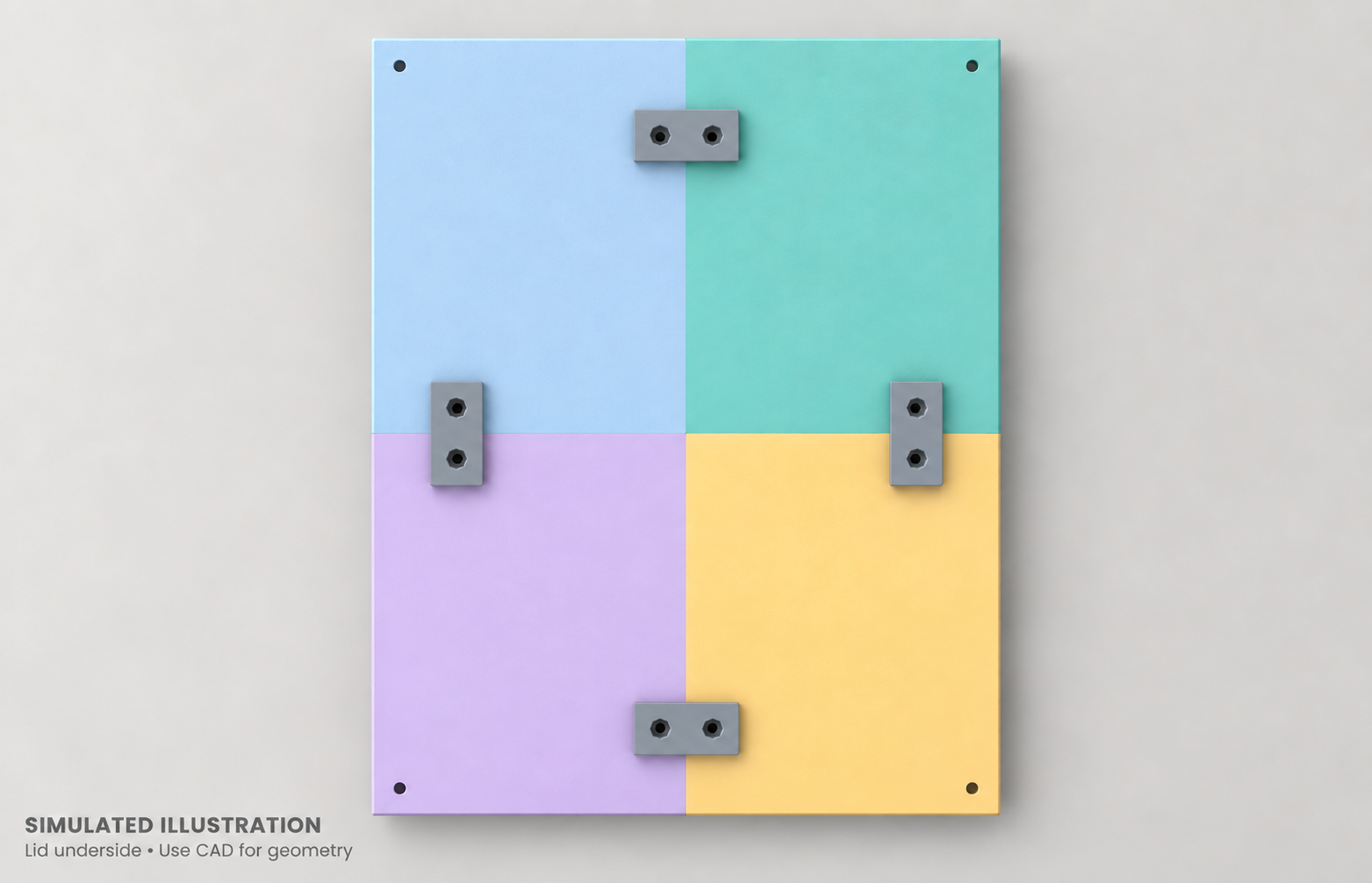
PARTS Four R2_lid quarters and four remaining R2_joiners.
TOOLS Flat table, ruler, hand hex key and nut holder.
FASTENERS Eight seam positions: compare M3 × 10 (H04). Four corner/post positions: compare M3 × 10 or 12 (H05). These are conditional lengths, with different nut-seat spans.
1. Arrange the four roof quarters exterior-face down on the table. Keep their corner/post holes at the outside corners and the two seam-hole systems aligned.
2. Bridge each of the four lid half-seams with an underside joiner, with its flat face against the lid. Align both 18 mm-spaced screw axes before starting either screw.
3. Use the same 6.3 mm nominal head-seat-to-nut-seat basis for each lid seam, then include the actual nut and any washers. Hold the underside nuts during removal.
4. Turn the assembled lid over with support. Slide and support the measured M3 nuts through the four inward X-facing upper post slots, with flats aligned to the 6 mm width; then trial-place the lid. Its corner screws must engage those nuts, not printed plastic.
Back to contents ↑07 Inspect the camera nut-loading problem
Check the listed parts and fit requirements before starting.
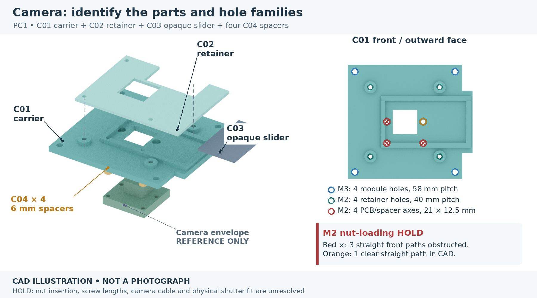
Actual C01 geometry and hole map. Three specified straight front nut-loading routes are obstructed by the rail/end-stop geometry.
PARTS C01 camera carrier; four intended M2 nuts if available. No camera required.
TOOLS Good light, calipers and a nonmetallic pointer.
FASTENERS Four M2 camera-board positions at (u,v) = (±10.5, −12.4/+0.1) mm relative to the lens centre.
1. Identify the camera-board holes close to the optical opening. Do not confuse them with the four M2 retainer holes at (±20,±20) or the four M3 shell holes at (±29,±29).
2. Inspect each nominal 4.4 mm-across-flats, 1.8 mm-deep M2 nut pocket from the front. The lower two and upper-left positions are partly overhung.
3. Leave the carrier unmodified. Do not force, melt or cut the rails to insert a nut, and do not assume a nut that fits once seated has a usable insertion path.
4. Record the carrier revision and this straight-insertion obstruction. No alternative tilted route has been validated. Continue with the independent shutter dry-fit and other modules while the camera-board fastener path is resolved.
Back to contents ↑08 Dry-check the camera shutter
Check the listed parts and fit requirements before starting.
Actual camera mechanism. C03 moves laterally inside the carrier guides; C02 retains it from the front.
PARTS C01 carrier, C02 retainer and C03 slider. T01 is optional as an initial local test.
TOOLS Clean flat table and ruler.
FASTENERS No screws needed for the supported dry-fit. C02 later uses four M2 fasteners, separate from the camera board.
1. Place C01 with the shutter guides facing up. Inspect the guide surfaces for loose debris, warping or obvious print damage.
2. Place C03 in the guides with its grip toward the retainer’s finger slot. Support C02 gently above it in its designed orientation; do not press down to make a warped part fit.
3. Move the blade slowly through its nominal 24 mm travel. Closed places solid blade across the opening; open clears the opening. Stop at binding or contact with a rail.
4. Lift off the unsupported retainer and keep the parts together. Record travel, binding and any visible rubbing. Do not call a visually solid blade proven optically opaque.
Back to contents ↑09 Prepare the camera mounting stack
Check the listed parts and fit requirements before starting.
Actual camera exploded view; four spacers sit between the PCB front mounting lands and the rear of C01.
PARTS C01–C04; four C04 spacers; actual Camera Module 3 Standard; matching front shell panel.
TOOLS Calipers, small hand driver and a supported parts tray.
FASTENERS 4 M2 camera-board + 4 M2 retainer + 4 M3 carrier-to-shell positions. None of the M2 hardware is supplied by an M3-only kit.
1. After Step 07’s hold and the actual screw-stack checks are resolved, verify the actual camera is Standard. Offer its mounting pattern to the carrier without loading the lens, connectors or components.
2. Put one 6 mm C04 spacer at each of the four PCB mounting lands. The camera screws enter from the PCB rear toward the carrier’s captive nuts. Include actual PCB thickness and any approved washer in the length calculation.
3. Before the blade is retained, confirm every camera screw tip remains below the moving blade’s underside. Do not choose a longer screw simply to get more protrusion.
4. Fit C03 and then C02 with four separate M2 fasteners at (±20,±20). Attach the complete carrier to the front-view-left shell opening with four M3 fasteners at (±29,±29), supporting inside nuts.
Back to contents ↑10 Fit the speaker to its cassette
Check the listed parts and fit requirements before starting.
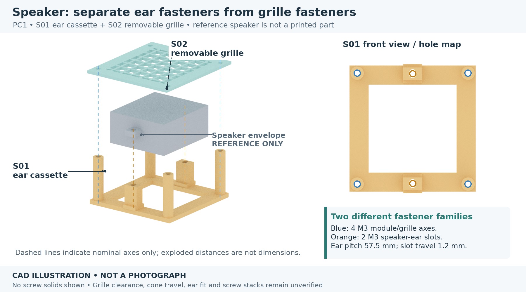
Actual S01/S02 geometry and the labeled manufacturer-based speaker reference envelope; no real fastener fit is implied.
PARTS S01 cassette, actual Seeed 114993346 speaker; T02 support section if present.
TOOLS Calipers, hand hex key and nut holder.
FASTENERS Two M3 ear bolts; compare M3 × 25 socket-cap (H08). Heads load from the rear into 6.2 mm-diameter, 3.2 mm-deep recesses. Actual heads, nuts and tip clearance must fit.
1. Check the actual speaker’s two ear-hole centres against the nominal 57.5 mm pitch. The printed ear passages have 1.2 mm slot travel; do not bend an ear to compensate for a mismatch.
2. Use T02, if available, to check whether the actual socket-cap head seats fully in the rear recess. A head protruding beyond the cassette’s panel-contact face will prevent seating.
3. Insert the two ear bolts from the rear before the cassette meets the shell. Set the speaker ears on the supports; route the lead freely through the central opening.
4. With the actual ear and any approved washer in place, select length from the measured stack. Start the front nuts by fingers and inspect full engagement without pulling or distorting the ear.
Back to contents ↑11 Mount the grille and speaker module
Check the listed parts and fit requirements before starting.
The four corner axes pass through S02, the cassette columns and the 3 mm shell panel. The two ear bolts are different joints.
PARTS S01 with speaker, S02 grille and the front-view-right module panel.
TOOLS Hand driver, nut holder and calipers.
FASTENERS Four M3 through-bolts on the 58 × 58 mm module pattern. Nominal front-head-seat to shell rear is 38 mm, before nut/washer allowance.
1. Offer S01 to the front-view-right aperture and confirm the two recessed ear-bolt heads are below its rear mounting face.
2. Place S02 on the four column ends with its four corner holes aligned. Check the speaker face is clear of the grille; the CAD body-plane gap is 3 mm, not a cone-motion qualification.
3. Compare the complete stack to the available screw length. A 30 mm screw cannot cross the nominal 38 mm stack and engage a nut. Keep this assembly supported and unfastened until correct longer hardware is selected.
4. Once qualified bolts are available, insert the four from the grille front, support the interior nuts and start all four before taking up looseness. Confirm later service removal does not pull on the speaker wire.
Back to contents ↑12 Verify the microphone board and guard
Check the listed parts and fit requirements before starting.
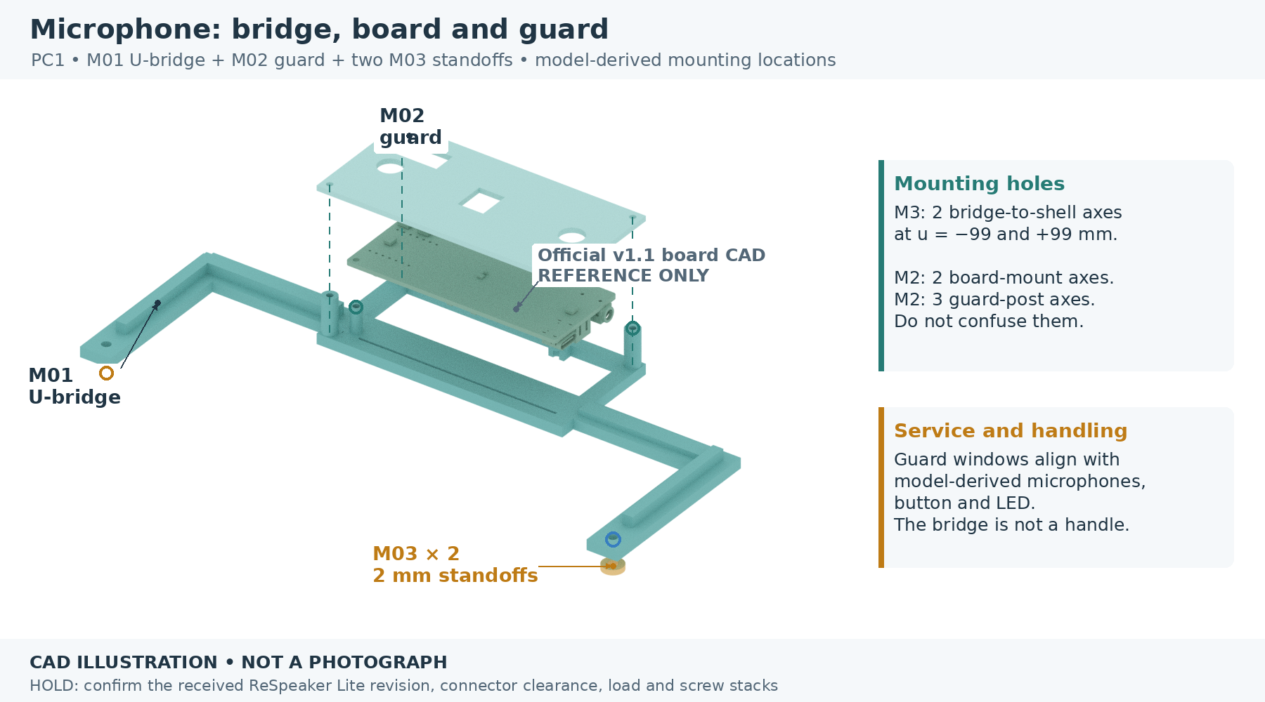
Actual microphone support geometry. The supplier STEP is a reference; the received board revision must match its asymmetric holes.
PARTS M01 U-bridge, M02 guard and actual USB-only reSpeaker Lite board.
TOOLS Calipers and a small hand driver.
FASTENERS 2 M2 board positions and 3 M2 guard positions. These use 2.4 mm printed clearance passages; exact lengths and head clearances remain open.
1. Compare the board to the design before mounting. The supplier wiki says 86 × 35 mm; the source STEP PCB is about 82.024 × 34.007 × 1.51 mm. Do not scale the printed mount or invent a four-hole pattern.
2. Orient the microphone-bearing underside toward the front; the component-rich side faces rearward. Confirm both asymmetric holes naturally match the two support axes.
3. Offer M02 without fasteners. Check the two microphone openings, shared button slot and indicator window against the actual board. The USB edge must remain open.
4. Only after that fit agrees, record the two board-fastener stacks and the three separate guard stacks. Use measured M2 hardware with safe board lands and no component contact.
Back to contents ↑13 Fit the microphone bridge to the shell
Check the listed parts and fit requirements before starting.
Actual U-bridge and spacer layout. The wide bridge is an accessory support, never a handle.
PARTS M01 assembly, two M03 2 mm spacers and the two upper-front shell/post positions.
TOOLS Hand driver, nut holder, actual USB plug/cable and ruler.
FASTENERS Two replacement M3 bridge bolts at Y=±99 mm; compare M3 × 25 socket-cap (H02). They replace existing upper-front bolts. Check the full actual stack before use.
1. Support the bridge independently. Remove one upper-front shell/post screw at a time while holding its nut. Keep the shell supported.
2. Place one M03 spacer between each bridge foot and shell. Align the bridge’s 198 mm-spaced mounting axes with the existing upper-front post axes.
3. Recalculate the original end/post screw stack with the added 2 mm spacer and 4 mm bridge base. Select a compatible longer M3 screw only after the actual nut and tip clearance check.
4. Dry-check removal and replacement of the complete lid, then actual USB plug insertion and unplugging. Keep the cable relaxed and reachable without pulling the PCB.
Back to contents ↑14 Check the small PF1 seam sample first
Check the listed parts and fit requirements before starting.
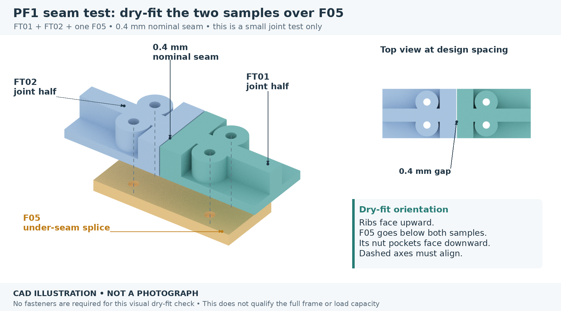
Actual source-derived sample halves above the real F05 splice. This is the three-piece dry-fit, not a completed base quarter.
PARTS FT01 and FT02 test halves; one extra F05 splice.
TOOLS Flat table, light and millimetre ruler.
FASTENERS None for this first alignment check. Frame joints ultimately use M4; the M3 kit does not qualify them.
1. Find and inspect both ribbed sample halves. Confirm each physical part is present, undamaged and identifiable; do not treat two filenames as two completed parts.
2. Place F05 underneath the halves with its hexagonal nut pockets facing down. Put the ribbed sides of FT01/FT02 up.
3. Keep the designed central seam, nominally 0.4 mm. Let the pieces sit naturally on the splice; do not squeeze the seam closed.
4. Look down through all four axes. Record whether the holes agree and both samples sit flat. Leave the test unloaded and without screws at this stage.
Back to contents ↑15 Lay out the four full base quarters
Check the listed parts and fit requirements before starting.
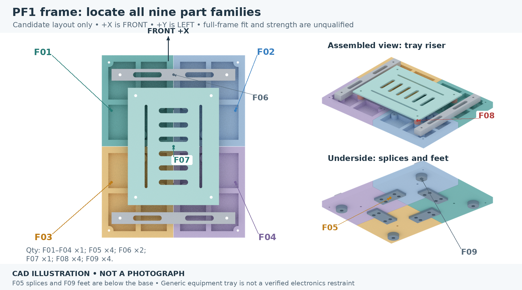
Actual full-size PF1 geometry, oriented with the robot front defined. The four quarter IDs are distinct.
PARTS F01, F02, F03, F04 and four accepted F05 splices.
TOOLS Flat table, ruler and calipers.
FASTENERS 16 M4 splice positions: four per splice. Candidate holes are 4.4 mm; underside pockets are nominal 7.5 mm AF × 3.5 mm deep.
1. Proceed only with accepted full quarters. The FT01/FT02 test halves do not replace F01–F04.
2. Arrange F01 front-left, F02 front-right, F03 rear-left and F04 rear-right, ribs up. Preserve both nominal 0.4 mm centre seams.
3. Position one F05 under each half-seam. Its four bolt axes must match the adjacent quarter holes; nut pockets face down and must remain accessible during fitting.
4. Trial-seat the actual M4 nuts and check one complete splice stack before repeating it. Use the frame length equation in the joint schedule; M4 bolt lengths are not supplied by the M3 kit.
Back to contents ↑16 Fit crossmembers, feet and the tray
Check the listed parts and fit requirements before starting.
CAD REFERENCE · Use for geometry and hardware
Actual PF1 frame parts. Crossmembers and their feet share fastener axes; the equipment tray is a separate removable assembly.
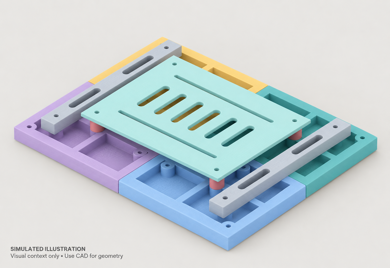
PARTS F06 ×2, F09 ×4, F08 ×4 and F07 ×1 with the accepted full base.
TOOLS Flat table, straightedge, calipers and appropriate hand tools for actual M4 hardware.
FASTENERS 4 shared M4 crossmember/foot bolts and 4 M4 tray/riser bolts. These are two different stack lengths, not eight identical bolts.
1. Place front and rear F06 crossmembers on the upper rib plane. Position the four F09 feet below their matching attachment axes.
2. Fit the shared through-bolt path through each crossmember/base/foot stack only after its dimensions are recorded. Check underside nuts and tips remain within the foot recess, so all four feet can sit flat.
3. Place four F08 risers at the tray axes, then offer F07. Check each hole, slot and tool path before selecting the four tray bolts.
4. Keep the tray empty. Its 180 × 140 mm envelope does not establish that the actual CanaKit case fits or is securely retained.
Back to contents ↑17 Check the body-to-frame interface
Check the listed parts and fit requirements before starting.
PF1 is the current printed structural candidate. The original shell is translated upward 11 mm in the digital inspection assembly.
PARTS Accepted shell and PF1 base; actual case only for external measurement, not installation.
TOOLS Support blocks, calipers and ruler.
FASTENERS Four M3 post-to-base positions at X=±129, Y=±99 mm; compare M3 × 25 socket-cap (H06). Already included in the shell count; the actual new-frame stack must pass.
1. Support the body over the empty base. Align its four post centres with the PF1 shell axes; do not use the old metal-deck drilling instructions.
2. Check all post bottoms contact the intended rib plane. Insert and support the measured M3 nuts in the four lower inward post slots while the lid is off. Stop if a slot or tool path is inaccessible.
3. Calculate the new bottom-attachment length from the PF1 base and post nut-seat stack. A historical metal-deck screw length cannot be assumed to fit the thicker printed frame.
4. Measure the actual CanaKit case, cooler, vents, feet and plugged-in cable envelopes separately. Leave case restraint, pass-throughs and strain relief pending until their geometry is established.
Back to contents ↑Joint schedule A · M3 screw locations
D is the nominal CAD distance between the modeled head-bearing surface and the nut’s near bearing face, before washers. Tip projection P = L − D − N − W, where N is nut thickness and W is total added washer thickness. P ≥ 0 is only a geometric screen: check usable threads, end chamfer, any unthreaded shank and the safe maximum projection. All dimensions below are millimetres.
| Joint / hardware ID | Qty | D | Catalog length to compare | Condition and location |
|---|---|---|---|---|
| H01 ordinary wall/post | 14 | 12.3 | M3 × 16 | 16 −12.3 −N −W is the tip projection. Head outside, nut inward. Excludes the bridge pair. |
| H02 bridge/post | 2 | 18.3 | M3 × 25 | Adds M01 4 +M03 2 to wall/post stack. Check inward tip and head bearing. |
| H03 wall seam joiner | 8 | 6.3 | M3 × 10 | Two per inside joiner. 10 −6.3 −N −W must be nonnegative and safe. |
| H04 lid seam joiner | 8 | 6.3 | M3 × 10 | Two per underside joiner. Nut pockets point down. |
| H05 lid corner/post | 4 | 7.2 | M3 × 10 or 12 | 10 has 2.8 total allowance for N+W+projection; 12 has 4.8. Nut in top side slot. |
| H06 PF1 base/post | 4 | 19.0 | M3 × 25 | Bolt upward through 14 mm base and 5 mm to post nut seat. Check new frame stack. |
| H07 camera carrier/shell | 4 | 6.0 | M3 × 10 | 3 mm C01 +3 mm panel; loose nut inside. No old carrier underneath. |
| H08 speaker ear | 2 | 19.8 | M3 × 25 | Rear head seat to front ear face. Check actual recessed head and ear stack first. |
| H09 grille/cassette/shell | 4 | 38.0 | No kit length | Every length in the identified kit is too short. Separate longer hardware required. |
Total: 50 M3 positions. H02 replaces two original wall/post positions. H07/H09 replace earlier module-carrier bolts. Only the two H08 ear bolts are added to the historical 48-position shell-plus-carriers count.
Example stock arithmetic only: if the 10 mm comparisons all pass and the lid corners use 12 mm, the above would use 20 × M3×10, 4 × M3×12, 14 × M3×16 and 8 × M3×25, plus four longer grille bolts. The kit would then have no 10 mm spares. This is conditional planning, not proof of fit.
Back to contents ↑Joint schedule B · M2 and M4
Front electronics and guard · 13 M2 positions
| Joint | Qty | D | Axes / requirements |
|---|---|---|---|
| Camera PCB / C04 / C01 | 4 | 8.32 | u=±10.5; v=−12.4/+0.1. Reference PCB 1.12 +spacer6 +pocket floor1.2. Nut-loading hold. |
| C02 retainer / C01 | 4 | 6.6 | u,v=±20. Four separate M2 axes; rear nut access through the shell aperture. |
| Lite PCB / M01 | 2 | 15.0 | (−38.52,52.42), (19.19,81.34). Actual board thickness and direction/head access unverified. |
| M02 guard / M01 | 3 | 20.0 | (−45,47), (−45,87), (45,87). Separate three-point mounting. |
PC1 printed M2 clearances are 2.4 mm. The camera’s specified nut envelope is 4.4 mm AF × 1.8 mm. Actual M2 hardware and board-safe head/washer contact are not established. An M3 screw is not a substitute.
Printed frame · 24 M4 positions
| Joint | Qty | D | Axes / critical limit |
|---|---|---|---|
| Base / F05 splice | 16 | 15.5 | 4 per splice. Head at rib/boss top; nut seats 1.5 mm below base underside. |
| F06 / base / F09 foot | 4 | 30.5 | (X,Y)=(±110,±82). Foot contact plane is 8 mm below base. No nut or tip below it. |
| F07 / F08 / base | 4 | 31.2 | (X,Y)=(±78,±58). Actual nut beneath base; retain underside access. |
Candidate M4 passages: 4.4 mm. Captive F05/F09 pockets: 7.5 mm AF × 3.5 mm deep. The foot joint’s screw is limited to 34 mm from its unwashered head seat to the floor-contact plane. Actual nut thickness and projection must fit inside the 3.5 mm recess. A head washer does not enlarge that recess.
Back to contents ↑Joint schedule C · locating every hole
Use these only to identify existing geometry. They are not drilling instructions. Current PF1 Z uses the base underside as zero; feet extend to Z=−8. The preserved body’s original reference coordinates are 11 mm lower.
| Interface | Exact CAD axes, mm | Approach / access |
|---|---|---|
| Side panels → posts | X=±129; Z=31/116; panel exterior Y=±108 | Along Y from outside to inward nut pockets |
| Front/rear panels → posts | Y=±99; Z=43/104; panel exterior X=±138 | Along X from outside; upper front pair also carries bridge |
| Side wall seam joiners | X=±9; Z=71, at each side wall | Two per seam; nuts face interior |
| Front/rear seam joiners | Y=±9; Z=71, at each end wall | Two per seam; nuts face interior |
| Lid seam joiners | (X,Y)=(±9,±80) and (±105,±9) | Eight screws from above, nuts underneath |
| Lid and base corner axes | (X,Y)=(±129,±99) | Four top and four bottom attachments; inward side-loaded post nuts |
| Camera module | Y=−83/−25; Z=41/99; four axes along X | Front-view left; 58 ×58 pattern |
| Speaker module / grille | Y=25/83; Z=41/99; four axes along X | Front-view right; 58 ×58 pattern |
| Microphone bridge | Y=±99; Z=104; axes along X | Existing upper-front shell/post positions |
| F05 splices · 16 axes | X=±18,Y=±48/±62; plus X=±63/±77,Y=±18 | Four splices below base; nuts down |
| F06 / F09 shared axes | X=±110,Y=±82 | Four combined crossmember/foot joints |
| F07 / F08 tray axes | X=±78,Y=±58 | Four tray/riser joints |
Do not confuse similar holes
• Camera: the inner four M2 holes mount the PCB; the (±20,±20) M2 group holds C02; the outer (±29,±29) M3 group attaches to the shell.
• Speaker: two central ear bolts load from the rear; four outside bolts run through grille, columns and shell.
• Frame: 4.4 mm holes are for the separate M4 joints. The four post axes use M3 and are already counted with the shell.
Back to contents ↑Record a fit before repeating it
Use one row per joint family and repeat a row when the material, part revision, head, nut or washer arrangement changes. “Pass” means this cold-fit check only; it does not release power, load or final tightening.
| Check / part IDs | Hardware and measurements | Result / date |
|---|---|---|
| Corner pair; identify post suffix | L____ head____ nut AF____ N____ W____ | ____ |
| Wall seam; joiner and panels | L____ N____ W____ tip projection____ | ____ |
| Lid seam / lid corner separately | L____ /____ underside and removal access____ | ____ |
| C01 nut insertion | Actual nut AF____ N____ insertion route____ | HOLD until resolved |
| C03 shutter dry travel | Travel____ no rub/binding____ C02 clearance____ | ____ |
| Camera mounting stack | PCB____ spacer____ screw____ tip clearance____ | ____ |
| Speaker ear recess | Head OD____ height____ ear____ L____ | ____ |
| Speaker grille common bolts | Actual total grip____ N____ W____ L____ | ____ |
| Microphone board / guard | Revision____ hole match____ access____ | ____ |
| Bridge + lid service | Spacers____ L____ no interference____ | ____ |
| FT01 / FT02 / F05 | Seam____ all four axes align____ no rocking____ | ____ |
| Full frame splice / foot / tray | Separate L____/____/____ feet flat____ | ____ |
| Body / PF1 / case planning | Four posts seat____ case restraint pending____ | ____ |
When something does not fit
1. Stop that joint and label its parts. Keep successful, unrelated fit checks separate.
2. Record the exact IDs, printed material and observed mismatch. Photographing a close-up with a ruler can help later, but never force assembly just to obtain a photo.
3. Do not drill, sand a functional locating surface, cut a nut slot or substitute a different screw diameter without a reviewed revision.
4. Keep the original piece and record. A corrected design must be checked against both the original and the new physical interface before repeated copies are made.
Back to contents ↑Sources and design authority
Interactive edition, 7 October 2026: three reference-based AI-generated contextual illustrations accompany the unchanged CAD diagrams in Steps 05, 06 and 16. They are simulated, not photographs or precision geometry. Use CAD and the written checks for dimensions, holes, hardware and fit. No engineering hold was resolved by generating these images.
This edition follows the current all-printed stationary configuration: 24 R2 shell +13 PC1 front-module +19 PF1 frame pieces. Older metal-deck, PiCar-X, Wide-camera and mobility drawings remain historical references, not extra assembly parts.
[S2] Preserved BC1 body assembly and fit guide
[S4] Identified VGBUY M3 kit: Amazon B0D1XJ766V
[S5] Camera Module 3 Standard mechanical drawing
[S6] Speaker 114993346 manufacturer drawing
[S7] reSpeaker Lite official specification and reference model
Geometry and illustration provenance
The new step figures use the preserved individual R2 meshes, PC1 assembly meshes and supplier reference envelope, and PF1 meshes at their documented transforms. Exploded spacing and colors are explanatory only. All new illustrations are marked as CAD, not photographs. The hardware image is the seller’s catalog image for S4.
The 6 October read-only geometry audit checked the R2 OpenSCAD source, PC1 CadQuery source and exported C01 STEP, and PF1 CadQuery source. It added the camera straight-insertion obstruction and exact nut-seat/stack distances to this manual. No source design was altered. Real fasteners, print variation, electrical operation, optics, acoustics, heat and load remain physical checks.
AM1 Public Edition is an editable mechanical-fit manual. After the camera nut path, actual hardware stacks and physical inventory are resolved, revise the affected steps and record the accepted lengths beside each joint. Do not silently turn a conditional comparison into a final screw specification.
Back to contents ↑