No metal structural frame. PF1 adds 19 new printed pieces to the 37-piece existing body. The CAD and numbered layouts are available for review, but the full candidate is not ready to print until material, real-kit fit, joints and toolpaths are qualified.
The initial frame is stationary. Final case restraints, cable fittings and motor/caster/battery mounts remain unresolved. The old metal-deck baseline stays archived.
The 19 new printed-frame pieces
Nine installed types plus two small joint-test types. Quantities below are for the stationary candidate, with physical fit and load tests still on hold.
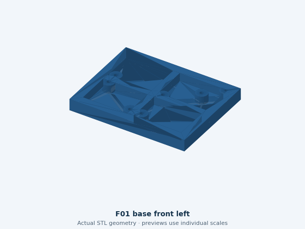
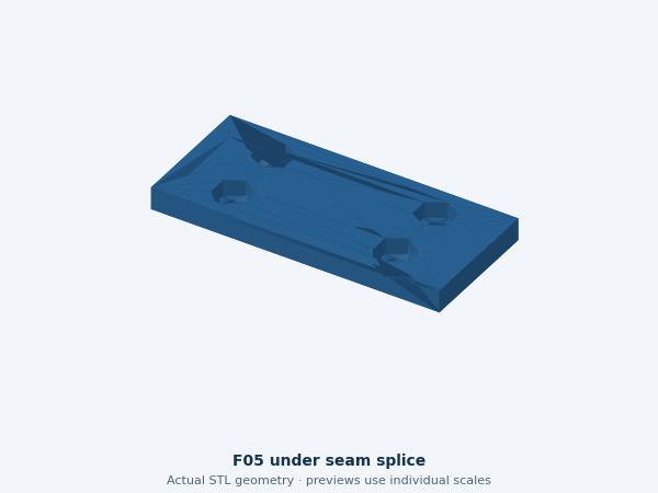
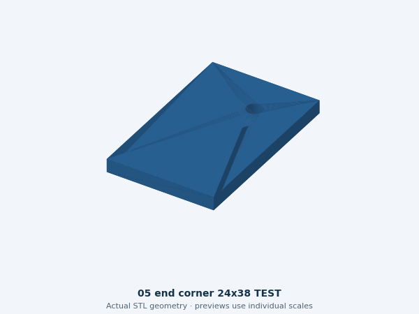
F01_base_front_left
F01 base front left
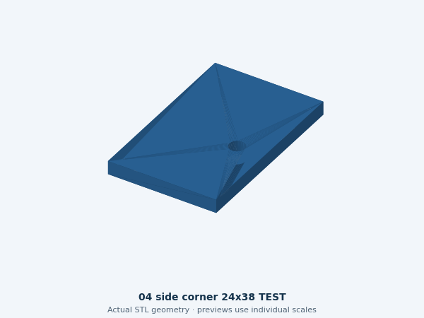
Ribbed quarter base with nominal shell, joint, crossmember and tray attachment holes. F01 base front left
1 installed · 139.8 × 109.8 × 14 mm
Orientation, material and fit gate
Orientation: Broad floor on bed; ribs upward.
Material: PETG candidate; exact spool/profile unconfirmed. No structural or thermal qualification.
Supports and brim: not sliced; inspect actual overhangs and nut pockets. The plate plan reserves 8 mm outer brim space without prescribing slicer settings.
Fit gate: actual screw/nut/head stacks, clamping, load/creep, case retention and heat tests remain unverified.
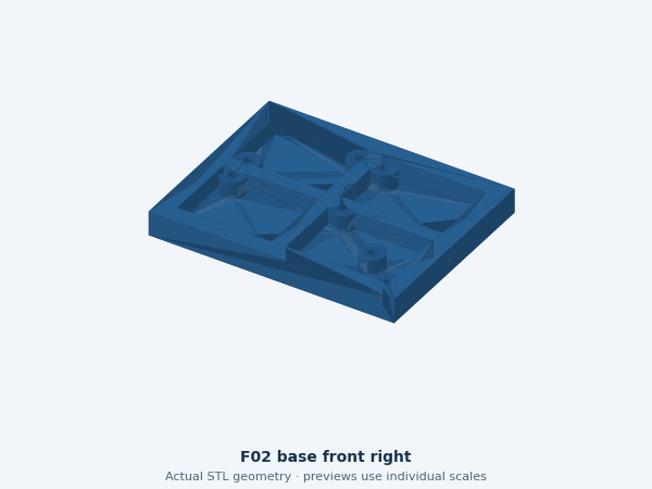
Ribbed quarter base with nominal shell, joint, crossmember and tray attachment holes. F02 base front right
1 installed · 139.8 × 109.8 × 14 mm
Orientation, material and fit gate
Orientation: Broad floor on bed; ribs upward.
Material: PETG candidate; exact spool/profile unconfirmed. No structural or thermal qualification.
Supports and brim: not sliced; inspect actual overhangs and nut pockets. The plate plan reserves 8 mm outer brim space without prescribing slicer settings.
Fit gate: actual screw/nut/head stacks, clamping, load/creep, case retention and heat tests remain unverified.
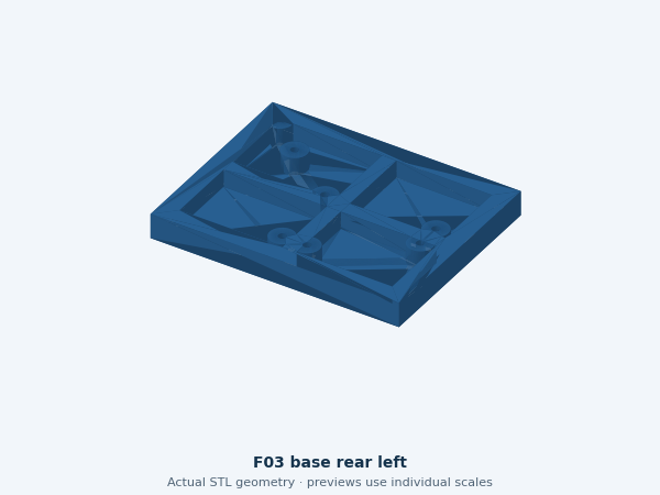
Ribbed quarter base with nominal shell, joint, crossmember and tray attachment holes. F03 base rear left
1 installed · 139.8 × 109.8 × 14 mm
Orientation, material and fit gate
Orientation: Broad floor on bed; ribs upward.
Material: PETG candidate; exact spool/profile unconfirmed. No structural or thermal qualification.
Supports and brim: not sliced; inspect actual overhangs and nut pockets. The plate plan reserves 8 mm outer brim space without prescribing slicer settings.
Fit gate: actual screw/nut/head stacks, clamping, load/creep, case retention and heat tests remain unverified.
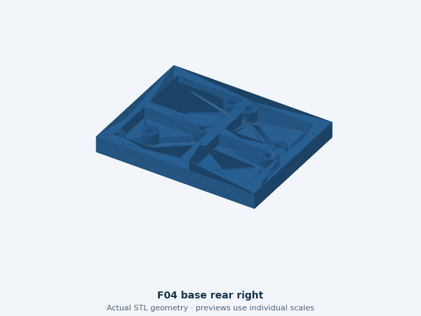
Ribbed quarter base with nominal shell, joint, crossmember and tray attachment holes. F04 base rear right
1 installed · 139.8 × 109.8 × 14 mm
Orientation, material and fit gate
Orientation: Broad floor on bed; ribs upward.
Material: PETG candidate; exact spool/profile unconfirmed. No structural or thermal qualification.
Supports and brim: not sliced; inspect actual overhangs and nut pockets. The plate plan reserves 8 mm outer brim space without prescribing slicer settings.
Fit gate: actual screw/nut/head stacks, clamping, load/creep, case retention and heat tests remain unverified.
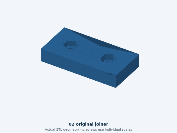
Overlapping underside joint brace; pockets face down in assembly. Verify actual M4 nuts and screw/head stacks.
4 installed · 64 × 28 × 5 mm
Orientation, material and fit gate
Orientation: Broad face down; nut pockets up while printing.
Material: PETG candidate; exact spool/profile unconfirmed. No structural or thermal qualification.
Supports and brim: not sliced; inspect actual overhangs and nut pockets. The plate plan reserves 8 mm outer brim space without prescribing slicer settings.
Fit gate: actual screw/nut/head stacks, clamping, load/creep, case retention and heat tests remain unverified.
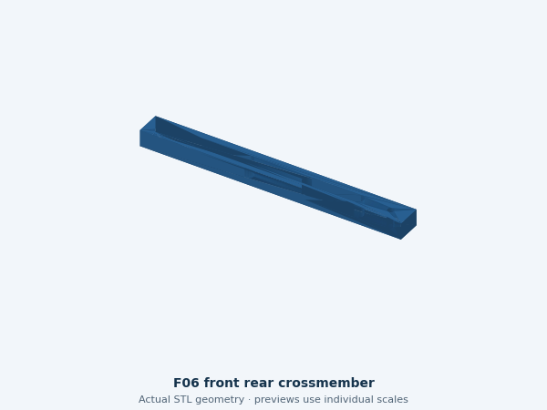
Connects opposite frame quarters across the width; not a motor mount.
2 installed · 190 × 18 × 12 mm
Orientation, material and fit gate
Orientation: Broad 190 × 18 mm face down.
Material: PETG candidate; exact spool/profile unconfirmed. No structural or thermal qualification.
Supports and brim: not sliced; inspect actual overhangs and nut pockets. The plate plan reserves 8 mm outer brim space without prescribing slicer settings.
Fit gate: actual screw/nut/head stacks, clamping, load/creep, case retention and heat tests remain unverified.
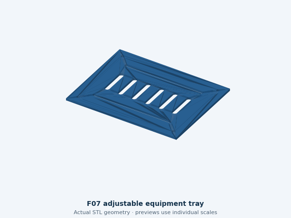
Removable ventilation/slot tray. Final case restraints and clearances remain measurement-gated; do not place a loose powered kit on it.
1 installed · 180 × 140 × 3.2 mm
Orientation, material and fit gate
Orientation: Broad flat face on bed.
Material: PETG candidate; exact spool/profile unconfirmed. No structural or thermal qualification.
Supports and brim: not sliced; inspect actual overhangs and nut pockets. The plate plan reserves 8 mm outer brim space without prescribing slicer settings.
Fit gate: actual screw/nut/head stacks, clamping, load/creep, case retention and heat tests remain unverified.
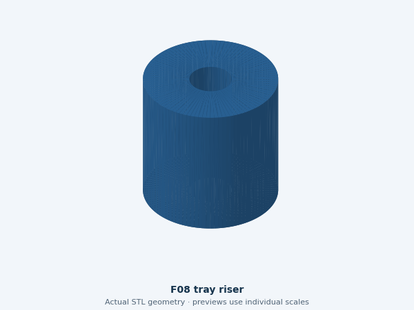
Four nominal 14 mm risers for the generic tray; real screw stacks required.
4 installed · 14 × 14 × 14 mm
Orientation, material and fit gate
Orientation: Ring base down; inspect through hole.
Material: PETG candidate; exact spool/profile unconfirmed. No structural or thermal qualification.
Supports and brim: not sliced; inspect actual overhangs and nut pockets. The plate plan reserves 8 mm outer brim space without prescribing slicer settings.
Fit gate: actual screw/nut/head stacks, clamping, load/creep, case retention and heat tests remain unverified.
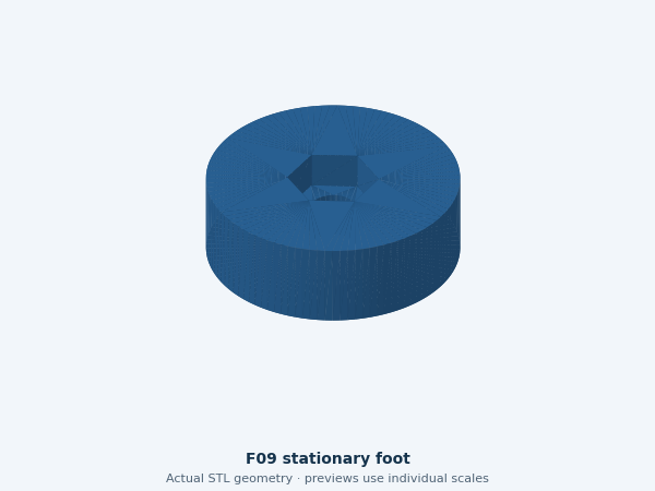
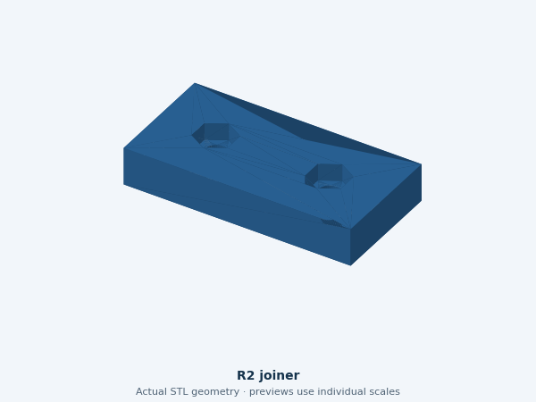
Stationary foot below a crossmember end, sharing its nominal through-bolt axis. Actual clamp stack and stability remain unqualified. Pockets face down in assembly.
4 installed · 24 × 24 × 8 mm
Orientation, material and fit gate
Orientation: Broad face down; nut recess upward.
Material: PETG candidate; exact spool/profile unconfirmed. No structural or thermal qualification.
Supports and brim: not sliced; inspect actual overhangs and nut pockets. The plate plan reserves 8 mm outer brim space without prescribing slicer settings.
Fit gate: actual screw/nut/head stacks, clamping, load/creep, case retention and heat tests remain unverified.
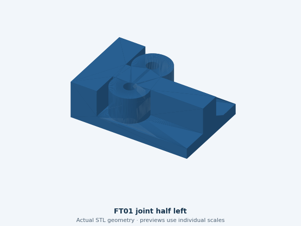
Source-derived small base-joint test half; does not qualify a complete frame.
0 installed · 44.8 × 30 × 14 mm; test specimen only
Orientation, material and fit gate
Orientation: Floor down, ribs up.
Material: PETG candidate; exact spool/profile unconfirmed. No structural or thermal qualification.
Supports and brim: not sliced; inspect actual overhangs and nut pockets. The plate plan reserves 8 mm outer brim space without prescribing slicer settings.
Fit gate: actual screw/nut/head stacks, clamping, load/creep, case retention and heat tests remain unverified.
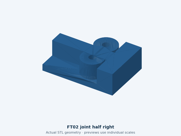
Opposite source-derived joint half; use with FT01 and one extra F05.
0 installed · 44.8 × 30 × 14 mm; test specimen only
Orientation, material and fit gate
Orientation: Floor down, ribs up.
Material: PETG candidate; exact spool/profile unconfirmed. No structural or thermal qualification.
Supports and brim: not sliced; inspect actual overhangs and nut pockets. The plate plan reserves 8 mm outer brim space without prescribing slicer settings.
Fit gate: actual screw/nut/head stacks, clamping, load/creep, case retention and heat tests remain unverified.
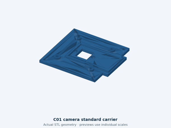
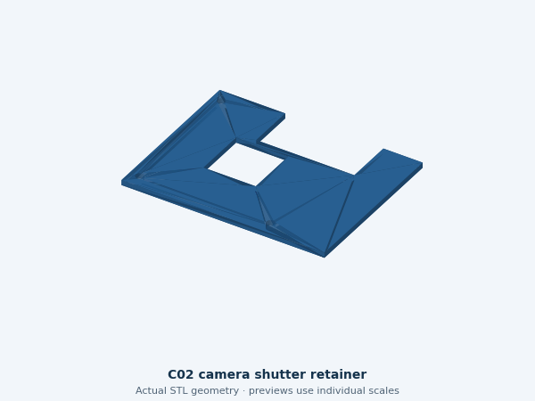
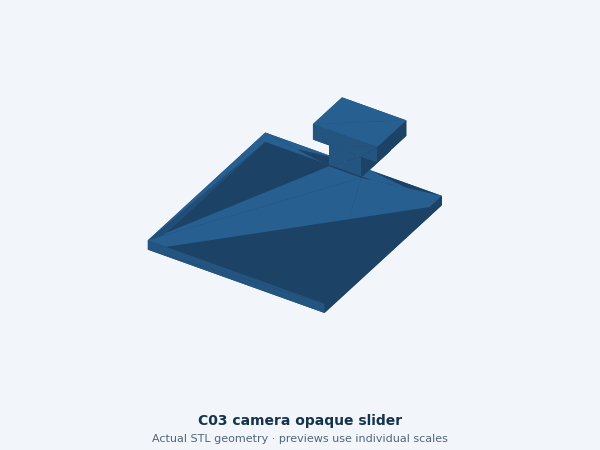
The original limited camera-shutter trial is C01 + C02 + C03, one of each. It tests the sliding mechanism only. It remains a separate trial, not a standing instruction to repeat it. Reconcile the actual private print register and accepted specimens before selecting another job. Do not interpret these downloads as a new print-send instruction.
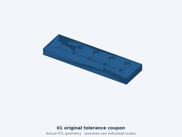
Before a full shell batch, use the hole-and-nut sample, short post and small matching wall samples. For the new frame, a joint coupon and a small loaded section must be designed and tested first. A passing shutter does not qualify a load-bearing base.
One printer job at a time: choose only the required STL files, keep millimetres and 100% scale, use the exact printer/nozzle/material profile, orient as below, and inspect every sliced layer. No universal support, brim, temperature or speed recipe has been qualified.
How the existing body fits together
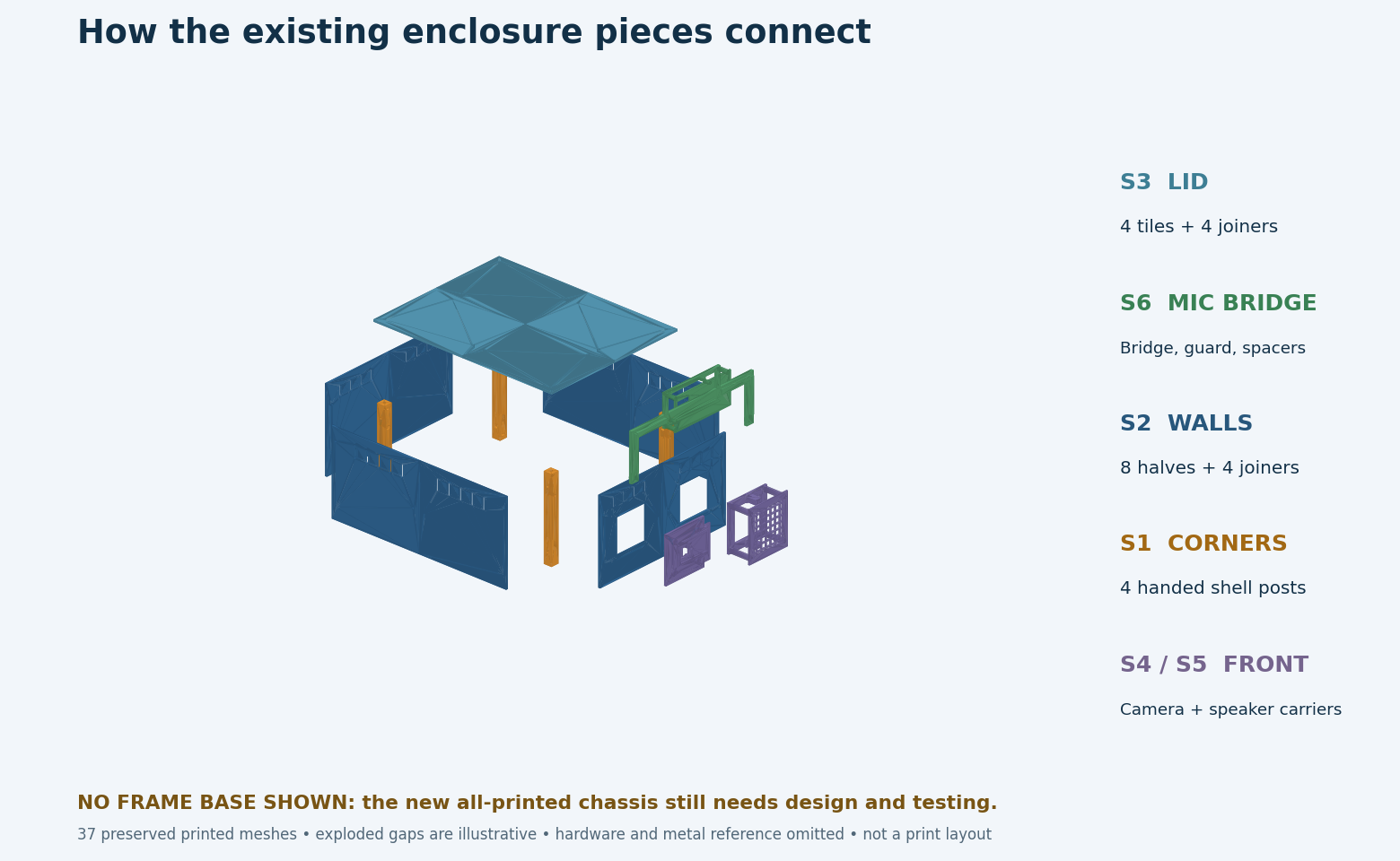
Actual existing geometry, separated only for explanation. The new printed base is intentionally absent because it has not been designed. Gaps in this illustration are not assembly clearances.
S1 · Corners: four different posts establish the enclosure corners. Their bottom attachment to the new frame is still unresolved.
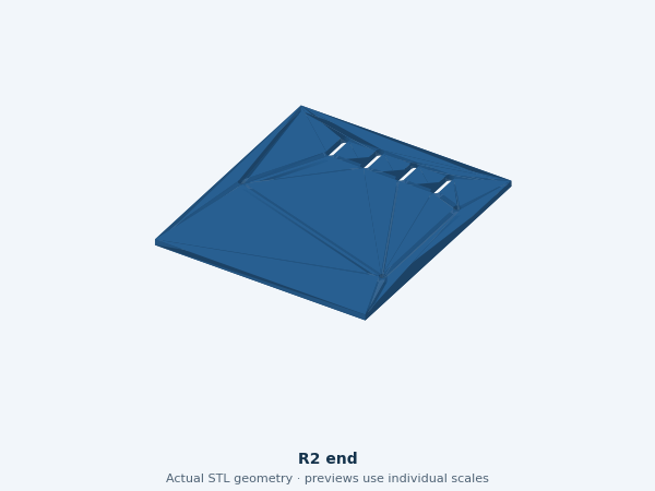
S2 · Walls: four long-side halves, two rear halves and two front-module halves attach to those corners. Four joiners connect the wall seams.
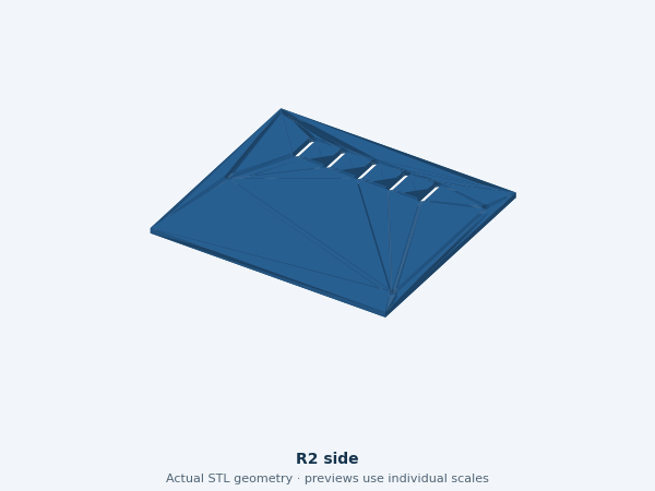
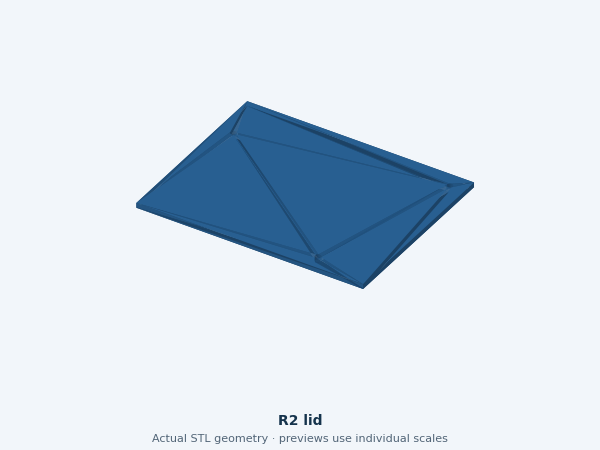
S3 · Lid: four lid quarters and four joiners make one removable top.
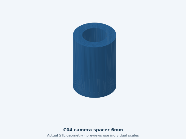
S4 · Camera: C01 carries the camera on four C04 spacers. C03 slides across the lens; C02 retains it.
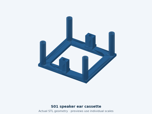
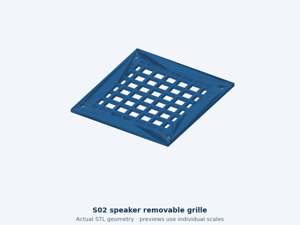
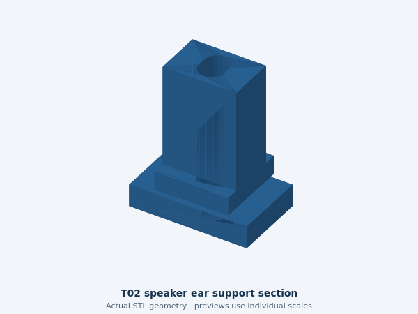
S5 · Speaker: S01 carries the enclosed speaker by its ears; S02 is the removable grille.
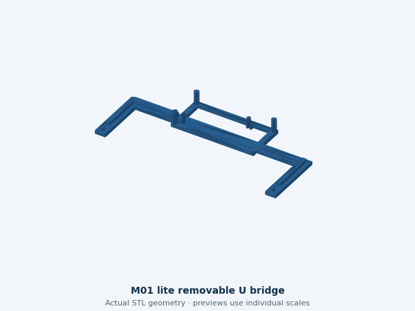
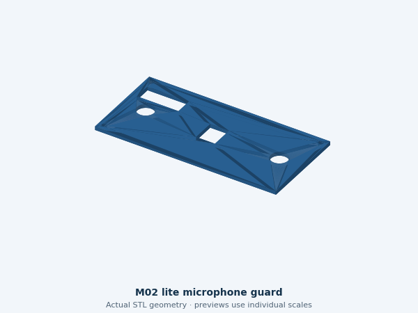
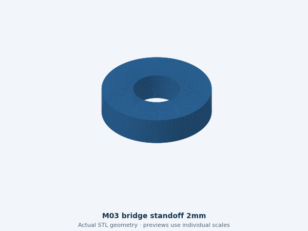
S6 · Microphones: M01 carries Lite, M02 guards it, and two M03 spacers sit at the bridge attachments. The bridge is not a handle.
Fastener lengths remain measurement-dependent. The old candidate has 50 M3 positions and 13 M2 positions; these are not approved purchase quantities for the new frame.
The 37 existing installed body pieces
18 STL types, 37 copies in the old BC1 assembly. A quantity of four means print the same file four times only after its fit gate passes. Handed corner posts each have their own file. These are existing candidates, not a complete new-frame print release.
Posts and connectors
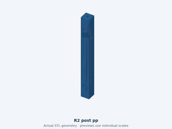
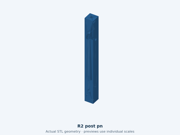
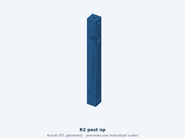
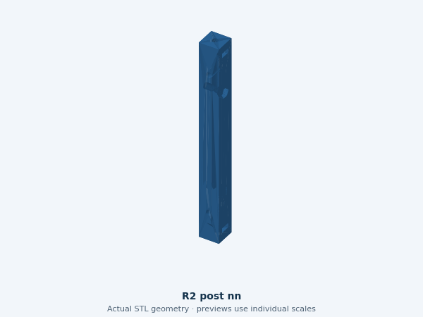
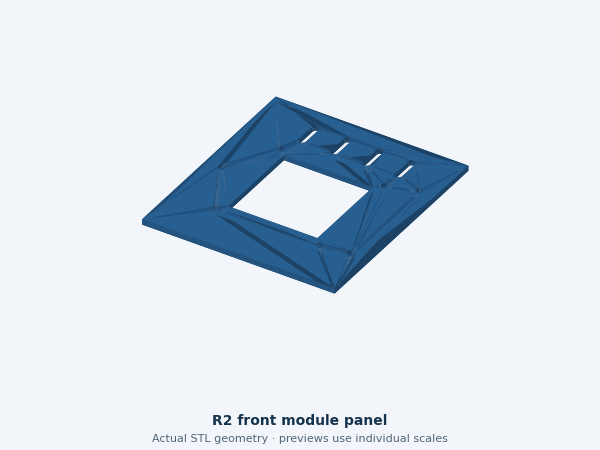
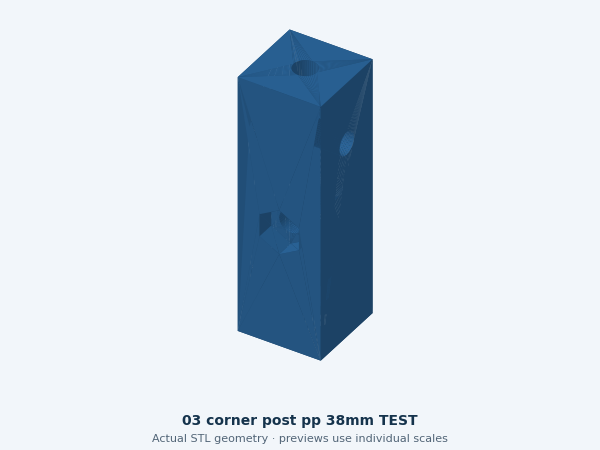
R2_post_pp
Corner post PP
One handed enclosure post at front / robot left. Supports the shell only; reassess attachment to the new printed frame.
1 installed · 12 × 12 × 120 mm
Assembly: S1
Print orientation, material and fit check
Orientation: Stand upright on its supplied bottom; holes face the matching panels. Review brim and bridging.
Material: Material/profile not qualified. The C01/C02/C03 black-PLA mechanism trial does not release the shell or frame material.
Supports: unqualified; inspect bridges, overhangs and captive-nut pockets in the actual slicer. Avoid trapped support inside functional holes.
Brim / printer: Nominal part fits AD5X and Creator 5 Pro; an 8 mm brim also fits their stated rectangular envelopes.
Fit gate: Measure real hardware, screw stacks and fit; physical test NOT RUN.
Carries Lite above the front. It is not a lifting handle or chassis frame.
1 installed · 210 × 96 × 18 mm
Assembly: S6
Print orientation, material and fit check
Orientation: Supplied base down; 210 mm width needs the printer/brim check.
Material: Material/profile not qualified. The C01/C02/C03 black-PLA mechanism trial does not release the shell or frame material.
Supports: unqualified; inspect bridges, overhangs and captive-nut pockets in the actual slicer. Avoid trapped support inside functional holes.
Brim / printer: 210 mm part + 8 mm brim each side = 226 mm. Does not fit AD5X in this orientation; Creator 5 Pro envelope allows it, subject to the real profile.
Fit gate: Identify actual Lite revision and holes, USB plug reach and microphone alignment; test bridge retention/acoustics.
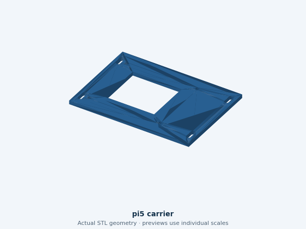
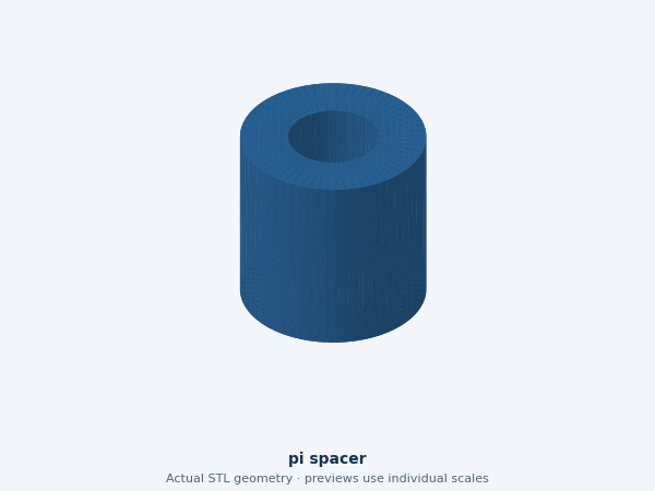
The bare-Pi carrier and spacer are preserved alternatives, with zero installed quantity in BC1. Keep the owned CanaKit assembled until its specific mount is designed.
pi5_carrier
Optional bare-Pi plate
Old bare-board option. Not a CanaKit case mount and not included in 37 pieces.
The Pi, camera, microphone electronics, speaker, cables, motors, bearings, tyres and fasteners are bought parts. “All-printed frame” means the structural frame and enclosure are printed; the electronics and wear parts are real components. Start with the five-item buy-if-missing bench list. Mobility hardware and exact frame fasteners remain separate.