BC1 · OUTER ENCLOSURE CANDIDATE
Existing body files
and the printed-frame candidate
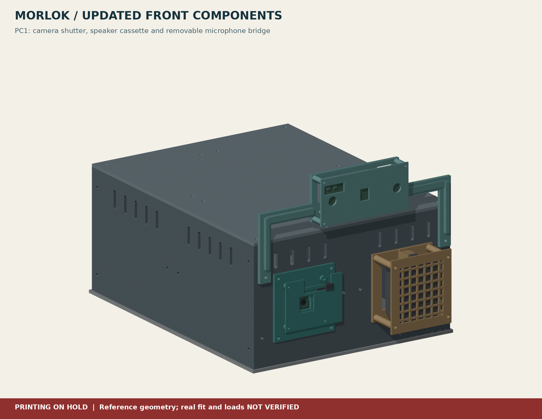
37 printed pieces. 18 individual STL types. The existing shell and camera, shutter, speaker and microphone mounts are now organized together, with editable sources and a fit-first assembly guide.
DESIGN REVIEW · 2 OCTOBER 2026
The next useful fixes
Keep the stationary bench as the first working robot. The 37-piece body is a useful preserved prototype, but printing more shell pieces will not resolve the audio software, internal mounts or cable fit.
- Adapt the existing voice prototype
The old configuration names PowerConf and opens 24 kHz audio output. The selected Lite has a documented 16 kHz maximum. Test actual formats and conversion; add intentional camera capture separately. Exact software gap and sequence
- Measure the real Lite before its bridge
The official v1.1 STEP used for PC1 gives a PCB about 82.024 × 34.007 mm, while Seeed’s wiki lists 86 × 35 mm. The model’s two mounting holes are asymmetric. This is an unresolved source mismatch, not proof the received board is wrong. Verify the revision, outline, holes, microphone openings and USB plug in hand; do not scale the model.
- Resolve case, cable and service space before the shell batch
Measure the assembled CanaKit with power, USB and camera leads attached. The optional bare-Pi plate does not retain that case. No final case tray, rear cable pass-through or strain relief is released. Keep fan intake/exhaust, SD-card reach, the power plug and AUDIO OFF reachable.
- Check acoustics before freezing the front layout
Seeed recommends comparable speaker-to-microphone distances, open direct sound paths and reduced vibration transfer. PC1 places its speaker to one side of the microphone pair; this needs an acoustic trial. Compare fan off/on where safe, low-volume playback and speech pickup, then test the final closed body. Echo cancellation alone does not prove this layout works.
- Simplify the next enclosure iteration only after measurements
Try a removable electronics tray and service panel as the next design proposal. Keep the current camera/shutter and audio carriers removable; use retained fasteners where feasible. BC1 has 37 printed pieces and 50 candidate M3 positions plus 13 M2 positions, so fewer seams and repeated fastener types could reduce assembly effort. This is a proposal, not a changed CAD release or a fastener order.
Download the full prioritized review and source links · Minimum working bench checklist
Reviewed published pages, preserved source code and CAD records. Existing mesh evidence has limited scope; physical fit, acoustics, cooling and AI hardware tests remain NOT RUN.
What belongs in this set
The 24-piece R2 enclosure is unchanged. PC1 adds 13 installed pieces. Two front-module panels replace two older plain end halves; they do not go on top of them. The optional bare-Pi carrier is separate, unplaced and not a mount for the CanaKit case.
| Individual STL | Qty | Print bounds, mm |
|---|---|---|
| R2_side | 4 | 135 × 120 × 3 |
| R2_end | 2 | 108 × 120 × 3 |
| R2_lid | 4 | 138 × 108 × 3 |
| R2_post_pp | 1 | 12 × 12 × 120 |
| R2_post_pn | 1 | 12 × 12 × 120 |
| R2_post_np | 1 | 12 × 12 × 120 |
| R2_post_nn | 1 | 12 × 12 × 120 |
| R2_joiner | 8 | 36 × 18 × 6 |
| R2_front_module_panel | 2 | 108 × 120 × 3 |
| C01_camera_standard_carrier | 1 | 72 × 66 × 5 |
| C02_camera_shutter_retainer | 1 | 62 × 48 × 1.6 |
| C03_camera_opaque_slider | 1 | 22 × 27.5 × 5.9 |
| C04_camera_spacer_6mm | 4 | 4.2 × 4.2 × 6 |
| S01_speaker_ear_cassette | 1 | 66 × 67.5 × 33 |
| S02_speaker_removable_grille | 1 | 66 × 72 × 2 |
| M01_lite_removable_U_bridge | 1 | 210 × 96 × 18 |
| M02_lite_microphone_guard | 1 | 96 × 46 × 2 |
| M03_bridge_standoff_2mm | 2 | 8 × 8 × 2 |
| Total | 37 | 18 individual types |
The joined printed body is about 311 × 216 × 180 mm, including the front modules and mic bridge. It is assembled from separate parts. Do not slice the complete assembly as a single object. The provisional 280 × 220 × 3 mm metal deck is not printable.
Choose the right printer envelope
Creator 5 Pro
The official bed is 256 × 256 × 256 mm. All individual candidate meshes fit this envelope, including an 8 mm XY brim allowance. This is the preferred machine for the 210 mm microphone bridge, after machine, material and toolpath review.
AD5X
The official bed is 220 × 220 × 220 mm. The parts fit nominally, but the microphone bridge plus an 8 mm brim is 226 mm wide. That combination does not fit. Do not shrink parts to make them fit a profile.
Bed bounds do not validate a sliced job. Check the actual usable area, nozzle, material, skirt/brim, supports and every toolpath layer. A limited PLA camera-shutter test does not qualify PLA for a warm closed electronics body. Earlier PETG settings remain untested starting guidance.
Official specifications checked 2 October 2026: Creator 5 Pro and AD5X
Historical BC1 fit and assembly order
Archive reference only: this sequence describes the old metal-deck baseline. Do not follow its deck/drilling steps for the new all-printed frame. Use the Every part page for the current design direction.
- Measure before choosing mounts
Identify the exact CanaKit case/cooler and measure it with cables plugged in. Leave the working Pi kit assembled. Complete the worksheet before final internal retention or cable openings.
- Start with the small interfaces
Use the tolerance coupon, short post/panel corner and module-opening sample. Test actual screws and nuts without force. A passing small sample does not prove a full-height post or assembled body.
- Check a full corner and front panel
Use the correct handed post. Side screws and end screws are at different heights. Confirm seam fit, nut access and front-module holes before a body batch.
- Build the loose shell on its verified deck interface
Fit four side halves, two plain rear halves and two front-module halves, then four internal wall joiners. The plastic supports the enclosure only. Motor, battery, caster and payload loads belong to separately engineered metal-deck mounts.
- Make one removable lid
Join the four lid tiles with four underside joiners. Its four corner screws release the complete lid. Support the underside nuts when separating tiles.
- Add camera and audio modules
The camera goes front-view left and speaker front-view right. Fit the mic bridge using its two spacers and existing upper front fastener positions. Verify the shutter, actual hardware and USB disconnect. The bridge is not a handle.
- Resolve the internal kit and cables
Do not close a body around an unsupported kit or pinched leads. Case retention, rear cable entry/strain relief, cooling paths and service reach are still measurement-gated.
- Test the stationary enclosure
Record real lid removal, camera view and shutter opacity, mic/speaker behavior, cooling, Wi-Fi and privacy access. Battery, drivetrain and powered movement remain separate.
Download the detailed assembly and fit guide · Download the test record
What the checks actually establish
A fresh read-only audit passed 32 existing individual STL files: closed edges, consistent winding, one connected component, no zero-area triangles, positive volume and bed contact. This includes installed types, test sections and optional bare-Pi pieces. The native assembly reopened with 24 separate shell meshes and 13 PC1 candidate meshes.
Earlier PC1 checks covered bounded solid intersections, shutter travel, the nominal lid-lift volume and an assumed USB corridor. They exclude real cable bends, screw stacks, received hardware, strength, optical performance, heat and acoustics. No physical fit or print quality is claimed.
Original R2 and PC1 geometry, source files and prior guides are preserved. The next design input is the actual CanaKit case/cooler and plugged-in cable dimensions.