Build the audio path first. Check it locally. Then add the camera. Each step tells you what to hold, where it goes and what the finished step should look like.
Microphones + speaker: Pi USB-A → data cable → Lite USB-C → Lite speaker socket → matched speaker
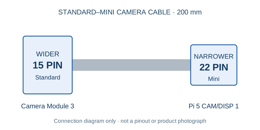
Camera: Pi CAM/DISP 1 → narrow 22-pin end → camera cable → wide 15-pin end → Camera Module 3
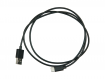
Power: existing verified Pi 5 supply → Pi USB-C power socket. No other power path.
1
Put only the first-build parts on the table
Gather: Owned Pi 5 CanaKit, B1–B3 for audio; B4–B5 when adding vision. A small Phillips screwdriver, masking tape and paper labels.
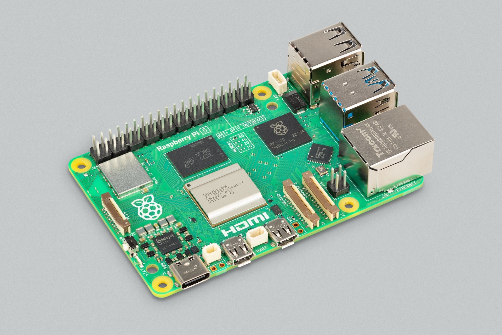
Manufacturer photograph: Raspberry Pi 5. Keep your existing case and cooling fitted if already assembled.
Shut down the Pi from its desktop, then unplug its USB-C power supply from the Pi. Disconnect other power sources. Do not work on a powered board.
Leave the working microSD card in place. Set the Pi, its matching case/cooler/supply, Lite board, speaker and data cable in separate groups. Put the robot-car kit, Pico, motors and batteries aside.
Check each model against the shopping photographs. Mark each line “have exact part” or “missing”; an old shopping record is not proof it arrived.
Finished state
You have the existing Pi kit and one of each audio part. Power is unplugged. Missing items are the only shopping items.
If this does not match your parts
If the Pi supply, case or cooler cannot be identified, photograph their labels before substituting anything. Do not buy another CanaKit.
Gather: B1 reSpeaker Lite, B2 speaker. Clean rigid nonconductive support; see the exact optional acrylic kit below.
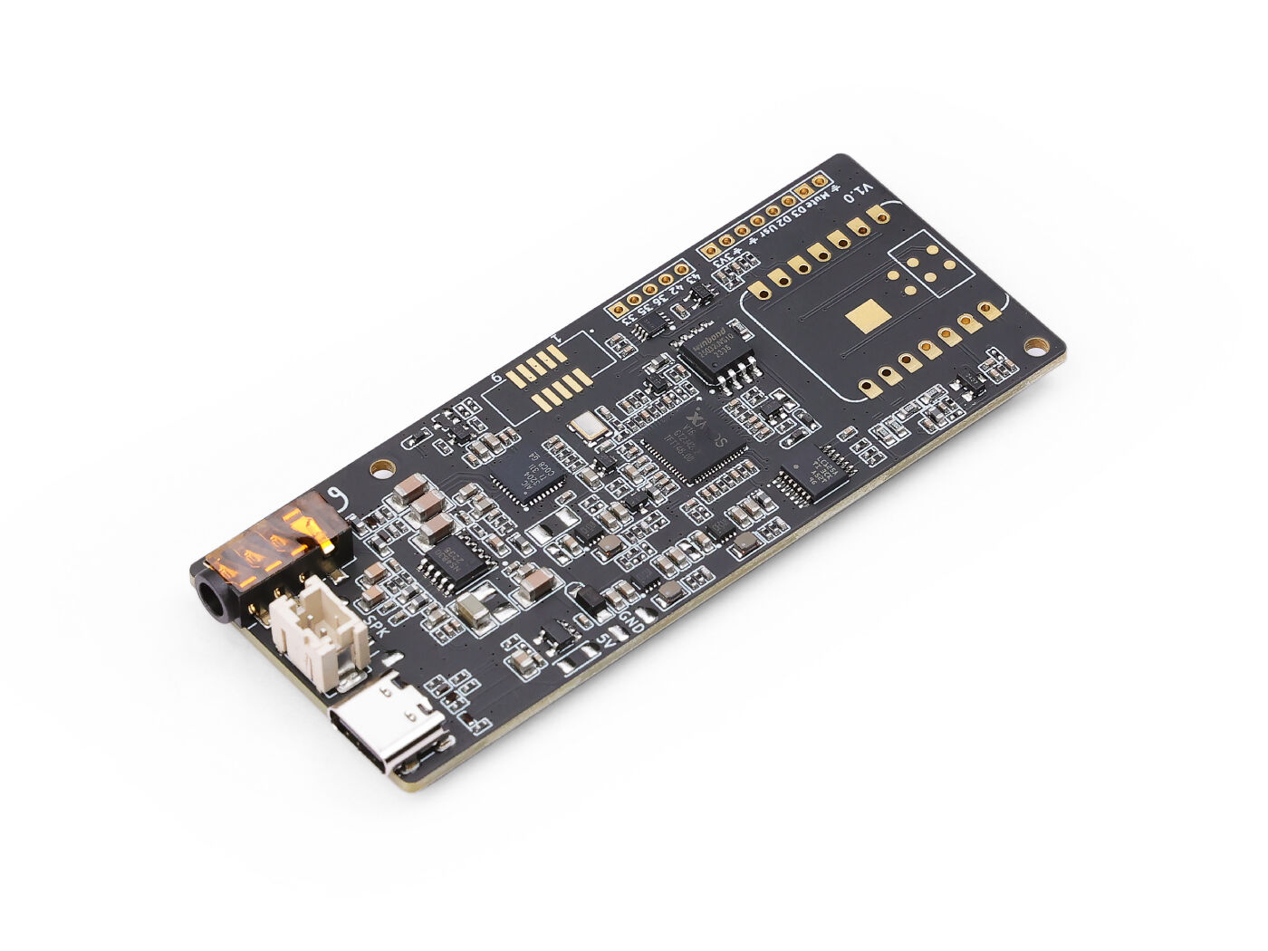
Manufacturer photograph: the USB-only two-microphone Lite board. The case is a separate item.
Place the speaker on its flat enclosure base with its sound opening clear. Support the Lite board so its underside cannot touch metal, screws or an antistatic bag, and neither microphone opening is covered.
For a tidy first bench, the matched Seeed acrylic enclosure 110991984 is an optional $5 buy-if-missing support. Assemble it with its supplied hardware using the linked maker video. It is temporary bench packaging, not a replacement robot body.
Keep the Pi fan away from the microphone openings. Leave the USB socket reachable by hand. The printed MORLOK microphone bridge and speaker carrier are later fit-test work.
Finished state
Both audio parts are supported, cannot slide into the Pi or loose metal, and the microphones and speaker opening are unobstructed.
If this does not match your parts
If you cannot support the bare board without covering its microphones or touching exposed contacts, stop here and use the matched enclosure. Do not run loose electronics on a conductive surface.
Gather: B1 + B2. No loose wires, soldering iron or extra amplifier.
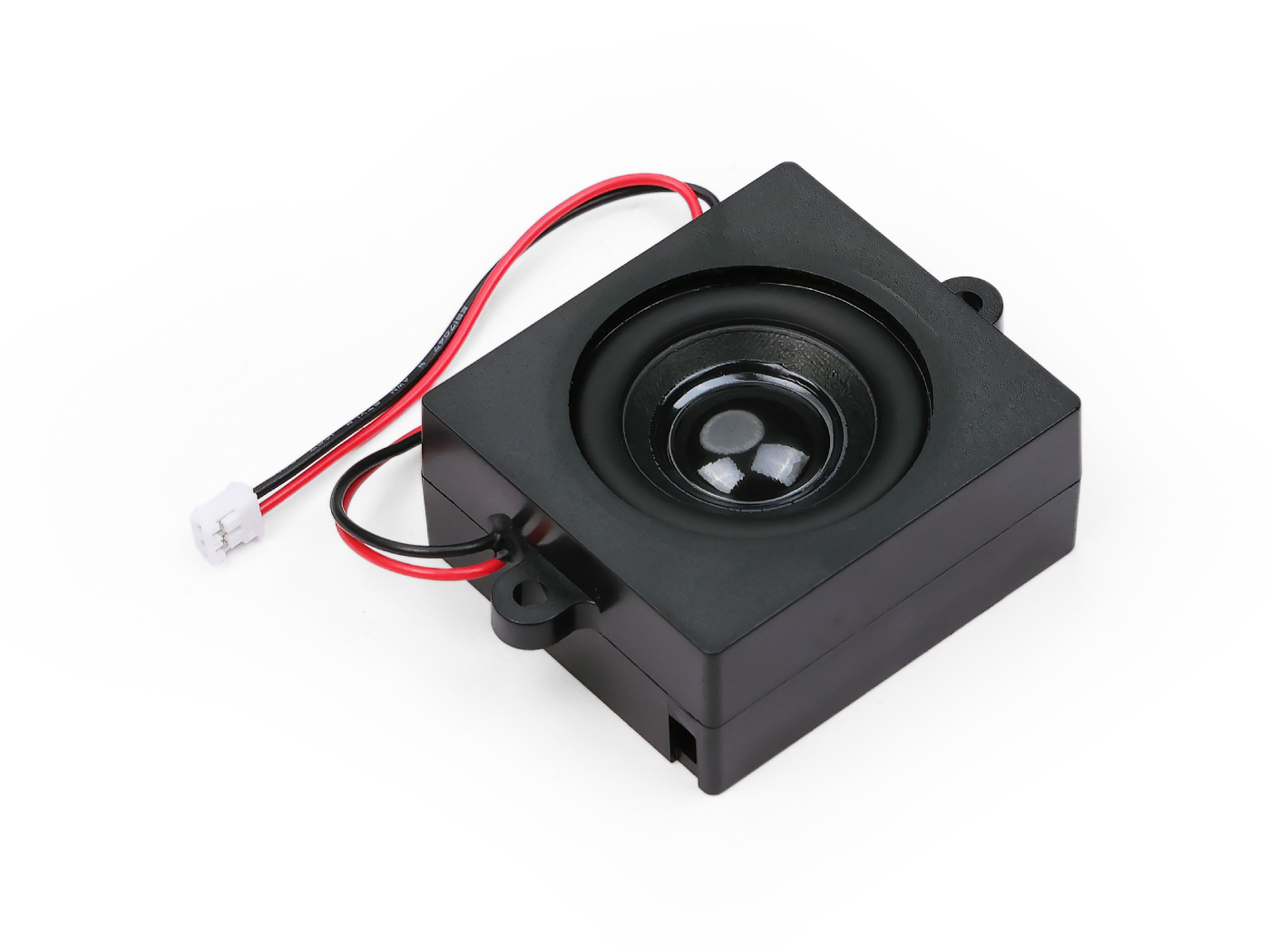
Manufacturer photograph: the selected enclosed speaker includes an attached two-wire lead and plug.
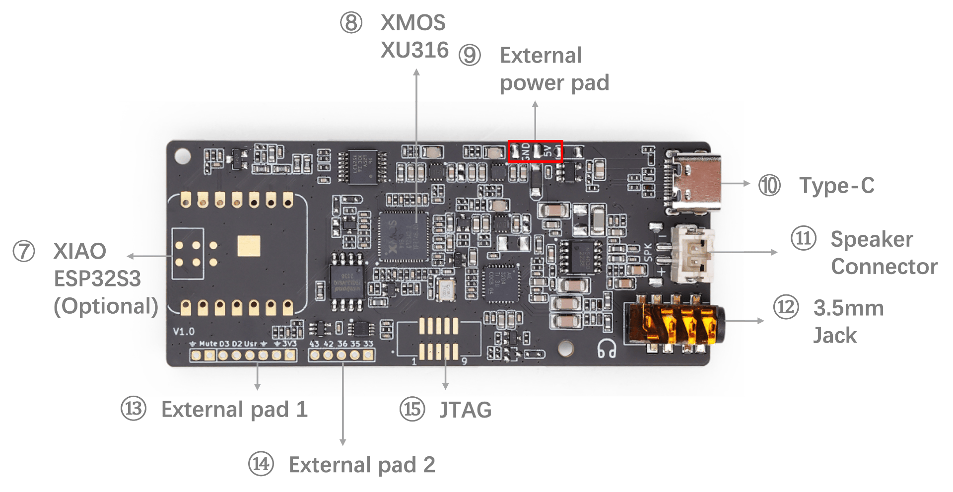
Keep all power disconnected. Find the small two-pin speaker socket on the Lite board; use the maker’s labeled hardware photograph below. It is not the round 3.5 mm headphone socket.
Hold the speaker plug by its plastic housing. Line up its molded guide with the socket and push straight in gently. Never push on the wires, reverse pins or force a mismatched plug.
Leave the round 3.5 mm socket empty. Put slack in the speaker lead so the board is not pulled sideways.
Finished state
The supplied speaker plug is seated straight, no conductor is exposed, and the wire has slack.
If this does not match your parts
Stop if the supplied plug differs from the socket. Seeed pairs these exact products, but its text does not specify connector pitch or pin polarity. Do not improvise an adapter. A 3.5 mm plug can mute the board’s speaker output.
Find connector 11 for the speaker and connector 10 for the USB cable
Seeed’s reference map includes an optional XIAO module. This build uses the board without XIAO and only its own USB-C port. Full-resolution manufacturer guide
4
Make the one USB audio connection
Gather: B3 data cable; B1 already connected to B2. Pi remains unplugged from power.
Manufacturer photograph: Type-A is the large rectangular plug; Type-C is the smaller oval plug.
Push the oval USB-C end into the Lite board’s own USB-C socket. USB-C works either way up. There is no XIAO daughterboard in this build.
Push the rectangular USB-A end into a free USB-A host port on the Pi. If it resists, turn the plug over; do not force it. Do not plug this cable into the Pi’s USB-C power socket.
Put a paper flag labeled AUDIO OFF around the cable near the Pi. Leave that USB-A plug exposed and reachable. Connect no external 5 V, GPIO, I2S or second audio power path.
Finished state
There is exactly one cable between Pi and Lite, plus the short Lite-to-speaker lead. Removing the labeled USB plug will remove the audio board’s only power/data path.
If this does not match your parts
If your cable has two USB-C ends or the device is a different reSpeaker model, it is not this connection path. Get the listed A-to-C data cable; no hub or adapter is needed.
Gather: The assembled audio path, existing verified Pi supply/cooling, working Raspberry Pi OS and a way to use its desktop.
Local test only: hearing your recorded voice is not yet an AI conversation.
Before any power-up, check that all parts are secure, dry and clear of metal; the supply is the correct Pi 5 supply; cooling is unobstructed; and no motor/battery wiring is attached. If a check fails, leave it unplugged.
When you choose to run the bench test, use the local audio test instructions on the Software page. Select “ReSpeaker Lite” as both microphone and output and start at low speaker volume.
Record five seconds saying “MORLOK audio test”, stop recording, then play it back. Unplug the labeled AUDIO OFF cable and check the device disappears and no new recording is possible.
Finished state
Expected: a clear recording plays through the small speaker; AUDIO OFF removes both recording and playback. These are expected results, not tests already performed.
If this does not match your parts
Not detected: try the known data cable and another Pi USB host port. Silent: select Lite output, remove anything from 3.5 mm socket, check low volume and the speaker plug with power off. Do not flash firmware as the first troubleshooting step.
Replace the camera’s wide ribbon with the Pi 5 cable
Gather: B4 camera + B5 Standard–Mini cable. Fingertips only.
Connection diagram (not a photograph): the cable has a wider Standard end and a narrower Mini end. Use the actual contacts and latch, not cable color, to orient it.
Shut down the Pi and unplug its power again. Handle the camera by board edges; avoid the lens and small components.
If a ribbon is already attached to the camera, gently release the plastic locking flap at both ends and remove the ribbon. Do not pull a locked cable.
With the camera lens facing away from you, slide the WIDER 15-contact end into the camera socket. Metal contacts face the camera circuit board and away from the movable locking flap. Seat it squarely, then close the flap gently.
Finished state
The wide end is held straight in the camera socket. The narrow end remains free. The cable has a relaxed curve and no sharp crease.
If this does not match your parts
If the latch comes off, the cable is skewed, or the contacts do not align, stop. The Standard–Standard cable packed with many cameras is not the selected Pi 5 cable.
Gather: Pi 5 + attached camera/cable from step 6. Power disconnected.
Manufacturer photograph: Pi 5. Identify the printed CAM/DISP 1 label on your board before opening the connector.
Find the Pi 5 socket printed CAM/DISP 1. Both camera/display sockets can accept a camera; using 1 gives this guide one consistent choice. Do not use the small FAN connector.
Release the camera socket’s locking flap gently. Insert the NARROW 22-contact end straight, with the metal contacts facing away from the movable flap. Close the latch without bending the cable.
Keep the camera close beside the Pi so the 200 mm ribbon is not stretched. Support the camera by its board/mounting edges so the lens is free; do not balance it on the lens. If the case or cooler blocks access, use its own removal instructions rather than levering around it.
Finished state
One wide-to-narrow camera ribbon connects camera to CAM/DISP 1. Both latches are closed, cable slack remains, and the camera is stable.
If this does not match your parts
Stop if the Pi case traps the ribbon or no safe camera support is available. The PC1 camera carrier, retainer and shutter are a separate fit trial; do not force an unverified printed part or choose screw lengths by guesswork.
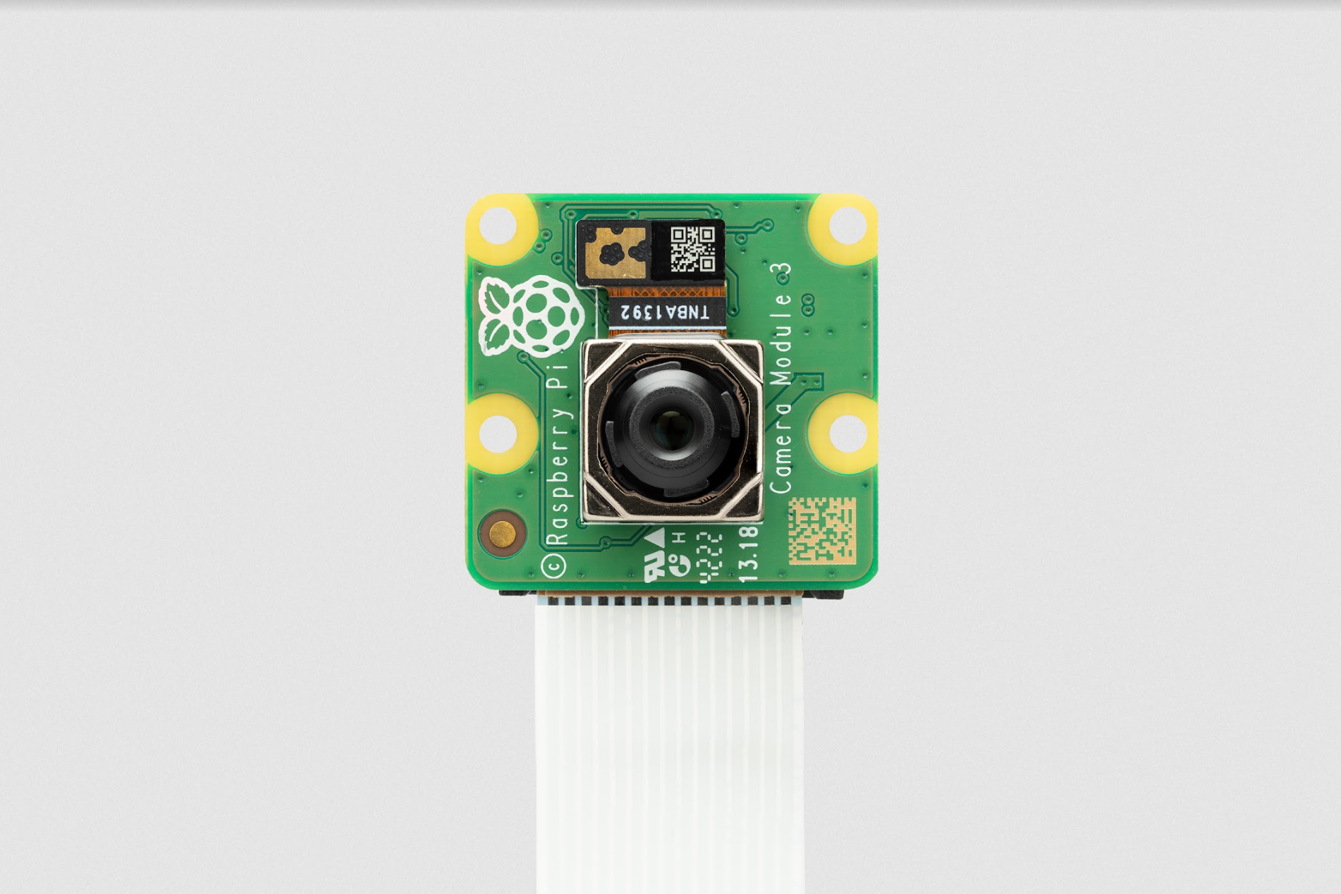
Manufacturer photograph: Camera Module 3 Standard. Keep the autofocus lens free of tape and pressure.
Repeat the power-off inspection from step 5, then run the local camera test on the Software page when ready. Point it at a non-sensitive object, such as a mug.
Expected result: the camera appears in the device list and one saved local picture opens clearly. Close an opaque cover in front of the lens without touching it; the next image should show no recognizable scene.
Keep the cover closed and AUDIO OFF unplugged when not testing. Leave automatic startup, cloud upload and AI controls off until the stationary application and visible capture controls are configured and tested.
Finished state
Expected: local microphone, speaker and camera checks pass independently. This is the hardware milestone; the custom push-to-talk AI application is the next software task.
If this does not match your parts
No camera: shut down and disconnect power before reseating either ribbon end. Blurry image: remove temporary lens protection, check lighting and let autofocus settle. Never reconnect a camera ribbon while powered.
The local hardware milestone is a recording, playback, a photo and working physical privacy checks. Connecting the AI application is the next software task. A moving robot is a later project stage.
Final camera/speaker/microphone mounts, print fit, fastener lengths and all motion wiring still need real measurements and tests. The PC1 camera carrier, retainer and slider remain a separate mechanism trial.
The parts-first, one-action-at-a-time structure follows the useful teaching pattern in official beginner build guides. All MORLOK instructions are written for the selected hardware; no older robot’s wiring has been reused.
Product photographs are manufacturer references, not photographs of received parts or a finished MORLOK. Existing realistic images are labeled concepts.