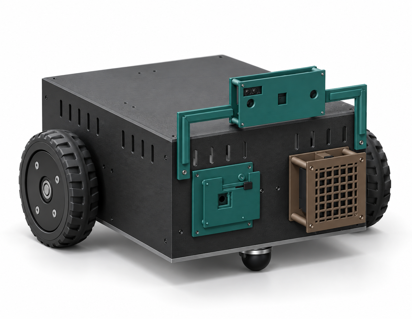
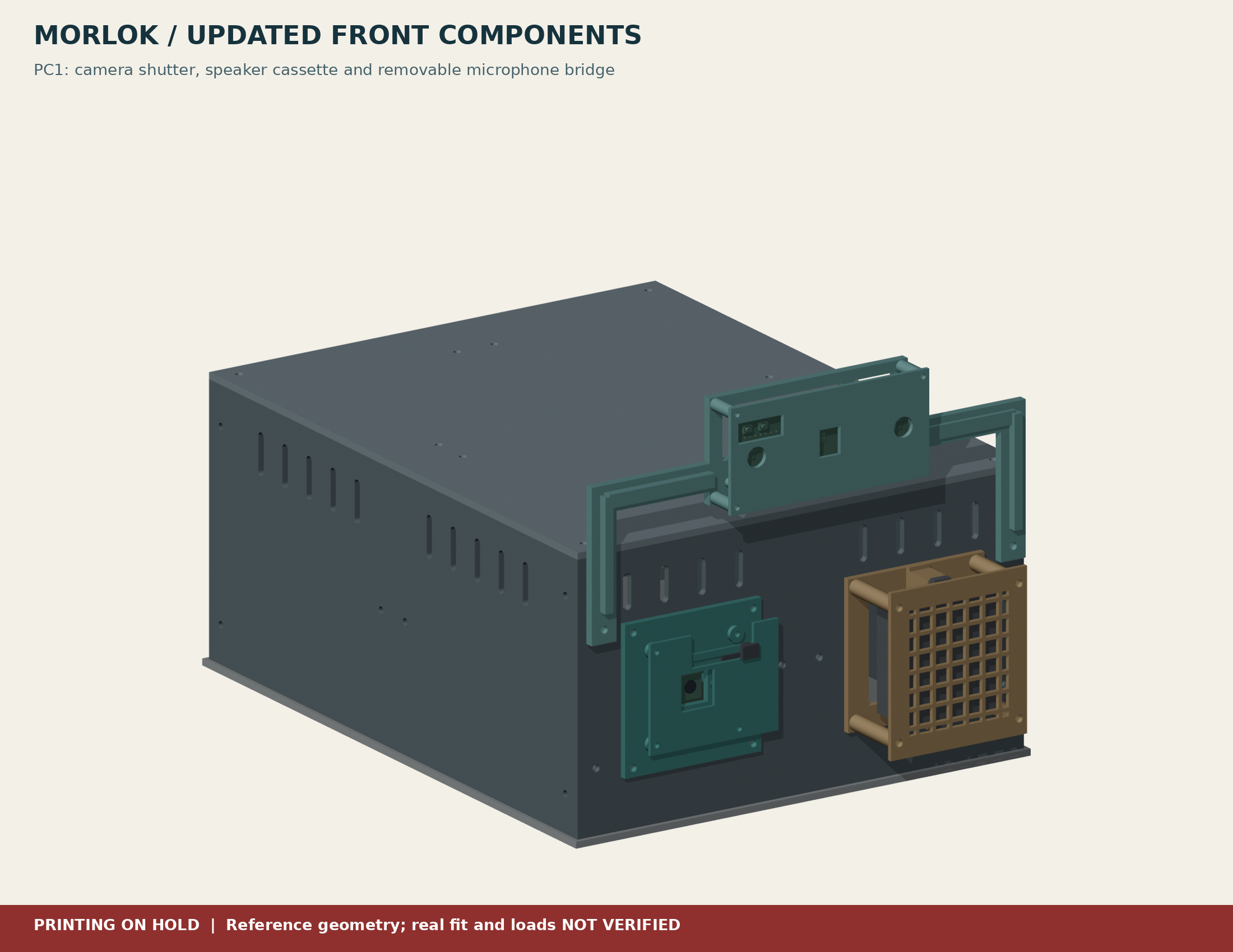
TF1 | 2 October 2026 | Dry-fit prototypes
After the current hold is cleared and a separate print release is given, start with the original tolerance coupon. Then check one lower corner and the existing front-module interface before committing to a body batch. Electronics are not needed for those checks. Three optional dummy pieces help you understand space, but cannot certify that a real component will fit.
This is an additive test kit grounded in the actual R1/R2 OpenSCAD and STL packages. It is not a new structural release. Physical printing, assembly and fit tests are NOT RUN. No G-code, printer job, wiring, motor power, purchase or motion command is included.
What is ready now
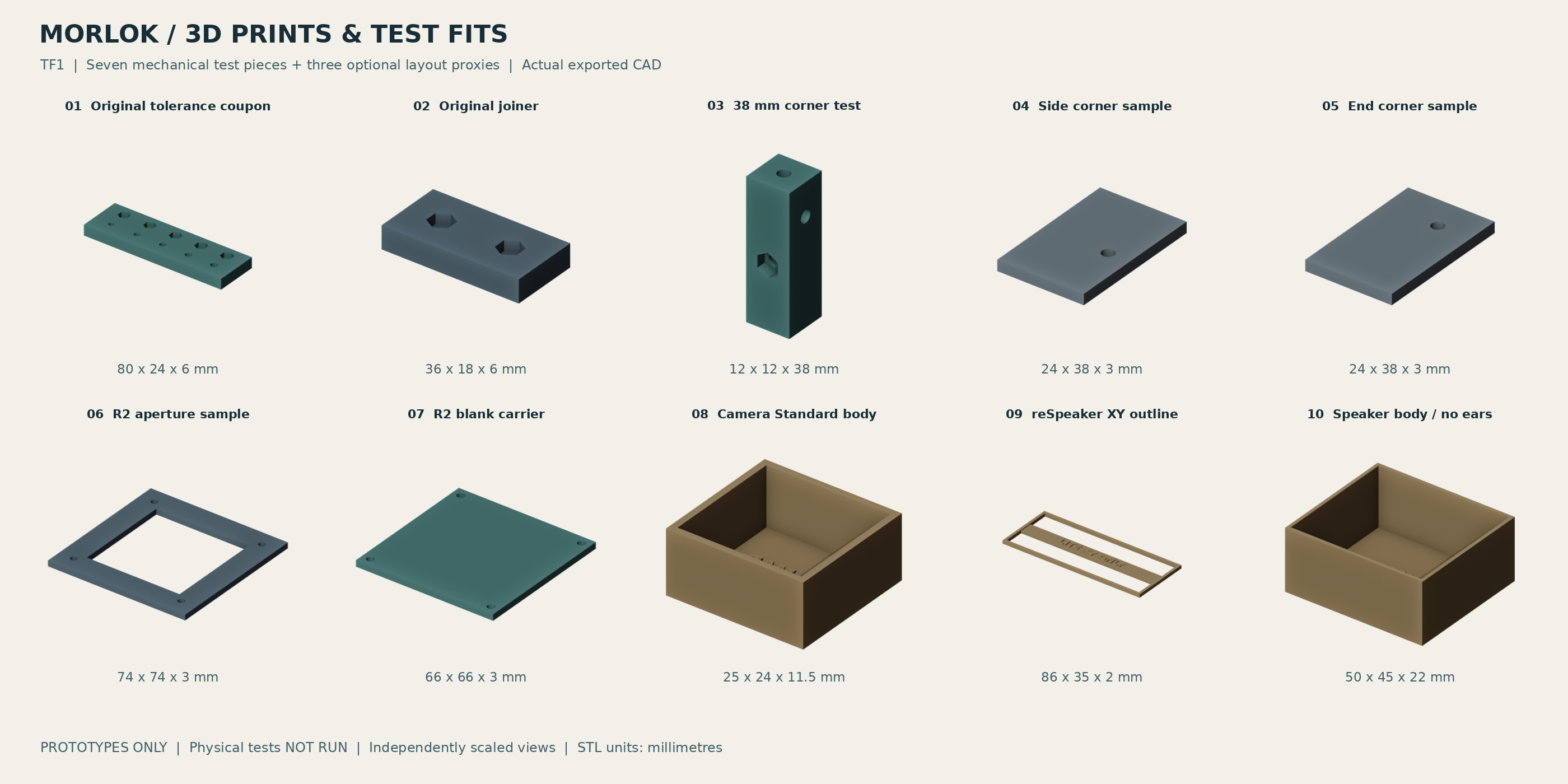
- 10 individual STL types in millimetres: 7 mechanical test parts and 3 optional component proxies
- Editable OpenSCAD plus unchanged R1/R2 source, a part manifest, staged quantities, blank measurement record and mesh/interface QA
- Unchanged individual shell STLs in future_shell_stl for the later 24-piece prototype body; do not print that whole batch yet
- Digital checks passed: all 10 test meshes are closed, consistently wound, single connected components, positive-volume and the expected size; the R2 50 mm aperture and 58 mm hole pitch were checked in exported geometry
Printer choice
Official Flashforge specifications: Creator 5 Pro has a 256 x 256 x 256 mm build volume; AD5X has a 220 x 220 x 220 mm build volume. Every individual TF1 part and preserved segmented shell part fits either nominal volume. This is a bounding-box check, not a tested slicer profile. The existing segmented body does not need resizing for Creator 5 Pro. Select the exact machine in the slicer.
Historical TF1 reference: its 280 x 220 x 3 mm metal deck is superseded by PF1 for the current stationary design. Preserve these test files as interface references only. PF1 still needs separate load, stiffness, fastener, creep and thermal qualification; no drivetrain mount is released.
Keep these boundaries
Only cosmetic shell loads belong on the source shell. Do not use its panels/posts to support motors, caster, battery restraint or lifting loads. Do not treat the short test corner as a robot part. No final camera mount, mic bridge, speaker cassette, shutter, drivetrain mount or battery restraint is released here.
1. Print only the next test
All quantities below are pieces, not filament spools or shopping pack sizes. Start with Step 1 alone. Print the rest only after the preceding checks pass.
| Step | Files / pieces needed for this step | New pieces | Cumulative test kit |
|---|---|---|---|
| 0 | Inventory printer, filament, measuring tools and sample M3 hardware | 0 | 0 |
| 1 | 01 original tolerance coupon x1 | 1 | 1 |
| 2 | 02 original joiner x1; 03 short post x1; 04 side sample x1; 05 end sample x1 | 4 | 5 |
| 3 | 06 R2 aperture sample x1; 07 original blank carrier x1 | 2 | 7 |
| 4 optional | 08 camera body x1; 09 mic-board XY outline x1; 10 speaker body x1 | 3 | 10 |
| ID | Nominal size, mm | Supplied print orientation | Material / purpose |
|---|---|---|---|
| 01 | 80 x 24 x 6 | Flat; hex pockets up | Intended body filament; tolerance |
| 02 | 36 x 18 x 6 | Flat; nut pockets up | Intended body filament; joiner |
| 03 | 12 x 12 x 38 | Upright as supplied | Intended body filament; short post |
| 04 | 24 x 38 x 3 | Flat as supplied | Intended body filament; side crop |
| 05 | 24 x 38 x 3 | Flat as supplied | Intended body filament; end crop |
| 06 | 74 x 74 x 3 | Flat as supplied | Intended body filament; aperture crop |
| 07 | 66 x 66 x 3 | Flat as supplied | Intended body filament; exact blank |
| 08 | 25 x 24 x 11.5 | Hollow/open face up | PLA/PETG; Standard body proxy |
| 09 | 86 x 35 x 2 | Flat; text up | PLA/PETG; XY only, arbitrary Z |
| 10 | 50 x 45 x 22 | Hollow/open face up | PLA/PETG; body proxy, no ears |
Starting print process, still unqualified
Use a calibrated single-colour profile, normally a 0.4 mm nozzle and 0.20 mm layers. Use the actual intended shell material for meaningful tolerance tests; PLA results do not qualify PETG. For original mechanical samples, the preserved R1 starting suggestion is PETG, 4 perimeters, 5 solid top/bottom layers, 30-40% infill. Use the filament maker's temperature range. For thin dummy walls, check that the slicer produces continuous walls; no infill cavity is needed.
Flat parts rest on Z=0. Consider a 6-8 mm brim for the upright post. Inspect its horizontal holes and nut-slot bridges. Do not fill nut pockets with support unless necessary; removing support can change the fit. Review the layer preview for missing walls, unsupported islands, elephant's foot and wrong units. No machine temperatures, speed or G-code have been validated.
Seven-part starter CAD solid volume: 46.465 cm3, about 59 g at an assumed PETG density of 1.27 g/cm3. All ten: 56.442 cm3, about 72 g fully solid equivalent. These are geometry-based planning figures, not a sliced filament estimate; actual infill, brims, supports, purges and failed prints change consumption. Print one colour to avoid unnecessary purge waste.
2. Coupon and corner checks
Have on the bench
Calipers, a ruler, a small deburring tool, an M3 driver and nut tool, a fine marker, a flat surface and sample measured M3 bolts/nuts. Keep chips away from electronics. No power or battery is needed. Use clean hands and eye protection when trimming plastic.
For the independent corner and module mockups, have up to eight M3 bolts and eight M3 hex nuts available: two for the corner, four for the module and two for the joiner pocket check. Reuse hardware between checks if needed. Starting source candidates are M3 x16 for corner walls, x12 for the 6 mm module stack and x10 for a full joiner/panel stack. These are not purchase-ready lengths: measure head, washer, nut, engagement and protrusion. Have eight suitable M3 washers for the module mockup if using one under each head and nut. A standalone joiner has no panel attached in this kit; it tests pockets, not the full panel seam.
Step 1: original coupon, quantity 1
Print 01 first in the intended body material. Mark hole diameters 3.0, 3.2, 3.4, 3.6 and 3.8 mm left-to-right along the row at local Y=8. Mark nut-pocket across-flat sizes 5.4, 5.55, 5.7, 5.85 and 6.0 mm along Y=18; pockets open upward. Their source pocket depth is 2.8 mm.
Record actual hole sizes and which accepts an M3 screw without force. Check measured nut fit and seating without splitting the pocket. The 3.4 hole / 5.7 AF source values are candidates. Remove only obvious burrs and record removal. Do not enlarge all geometry by scaling the STL: that changes hole pitch. If tolerances fail, revise a new source copy locally and retest.
Step 2: original joiner plus one lower corner, quantities 1 each
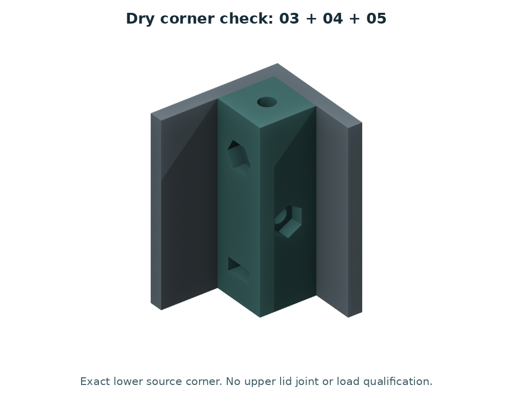
Mark 03, 04 and 05 TEST CUT with a pen. Stand 03 upright. Bring the long-side sample 04 to the post's outward Y face so its hole matches the post passage 17 mm above the base. Bring end sample 05 to the outward X face with its hole 29 mm above the base. The panels are intentionally different; do not swap hole heights. Insert inward-facing nuts by hand and check the two lateral bolts gently. Check the bottom nut slot separately, without applying a structural load.
The short post is the exact lower 38 mm of original post_pp. It includes the lower nut slot and both lower wall axes, but excludes the top lid attachment. The two panel crops retain original panel thickness and hole coordinates. Measure alignment, face seating, nut access, cracks and protrusion. This proves neither the upper corner nor the full-height post. Separately test the original joiner's two nut pockets and through holes; its full seam fit waits for a real panel.
3. Front interface and component space
Step 3: one aperture sample plus one blank
The 74 x 74 x 3 mm sample is cropped directly from the R2 front panel at local u=17..91, v=19..93. It retains the exact 50 x 50 mm opening and four 3.4 mm holes on 58 x 58 mm centres. It omits the front panel's original shell fasteners and vents. The blank is the unchanged 66 x 66 x 3 mm R2 carrier, so the nominal stack is 6 mm.
Centre the blank on the sample. You should have a 4 mm border around the blank on each side of the sample. All four bolts should pass simultaneously without bowing the parts. Measure the aperture, hole pitch, flatness, edge clearance and actual nut/washer stack. Support inside nuts during disassembly. Do not use the aperture crop as a installed front panel.
Step 4: optional layout proxies
08 Camera Module 3 Standard: outer dimensions 25 x 24 x 11.5 mm are the manufacturer's approximate body size. The hollow box is a space token, not a camera holder or optical model. Its label is inside; its 1.2 mm wall and 0.8 mm floor are print choices. It excludes the ribbon, connector service loop, shutter, spacers and autofocus/field-of-view keepouts. The Wide variant is taller at 12.4 mm and is not represented by this file. R2's preserved camera carrier was designed for Wide; this Standard proxy does not validate that carrier.
09 reSpeaker Lite USB-only SKU 107990273: 86 x 35 mm outside outline is sourced. The 2 mm token thickness is arbitrary, not PCB or assembly height. No mounting holes are invented. It excludes connectors, USB plug, cable bend, buttons, component height, XIAO, mic access and vibration isolation. Its 86 mm length is greater than the 66 mm carrier; this demonstrates why the intended removable upper mic bridge needs separate measured design.
10 Seeed speaker SKU 114993346: hollow 50 x 45 x 22 mm nominal body proxy only. It excludes mounting ears, holes, wire, plug and cable bend. Never insert actual hardware into the proxy's hollow centre: the exterior represents the body. A nominal 50 mm body dimension has zero clearance in a 50 mm aperture before print tolerances; this does not qualify a drop-through mount. A measured surface adapter, retention, baffle/gasket and grille remain to be designed.
Measurements needed before final electronic mounts
- Exact received camera variant, lens extent, PCB mounting lands, cable connector, relaxed bend and shutter travel; measure field of view with the real carrier
- Mic-board total height, underside projections, mounting-hole locations and diameters, microphone/button/LED coordinates, USB plug envelope and sole-disconnect access
- Speaker overall dimensions including ears, ear thickness, mounting centres and hole diameters, cone/grille keepout, wire exit, connector and bend envelope
- Actual Pi 5 cooler/case/HAT/plug envelopes, fan path, service loop and access; battery, drivetrain and structural restraints remain separate
A dummy can show an obvious collision. Passing a dummy test does not prove real fit, acoustics, cooling, optics, electrical isolation or safe operation. Record every physical result as NOT RUN until actually performed.
4. Later full body: preserved quantities
After the small checks and real-component measurements, build one full-height corner and one full replacement front panel before a full body batch. Preserve the original panel orientation, nut access and four distinct post variants. Use the historical M13/R2 instructions together with the latest project safety gates. Do not use assembly.stl as a whole-robot print.
| Preserved shell STL | Qty in complete R2 shell | Nominal mm |
|---|---|---|
| side.stl | 4 | 135 x 120 x 3 |
| end.stl | 2 | 108 x 120 x 3 |
| front_module_panel.stl | 2, replacing two R1 ends | 108 x 120 x 3 |
| lid.stl | 4 | 138 x 108 x 3 |
| post_pp, post_pn, post_np, post_nn | 1 each, 4 total | 12 x 12 x 120 |
| joiner.stl | 8 | 36 x 18 x 6 |
| TOTAL SHELL | 24 pieces | Deck and carriers excluded |
R1 has four plain end halves; R2 replaces two with module panels. Do not add replacement panels on top. The kit's original joiner may count toward the later eight only if it passes the same material and fit checks. The cropped tests and dummies count as zero installed body pieces. The coupon is one test piece, not a shell piece.
There are two front module positions. Blank carriers are 0-2 as needed; TF1 includes one for testing, reusable only if qualified. Future camera and speaker carriers, a mic bridge, camera shutter, spacers and controls add parts beyond the 24-piece shell. Their final quantities are not released because the actual parts and layouts are unmeasured. Avoid buying a whole fastener assortment against a speculative final count.
Historical shell fasteners: 40 M3 screws and 40 nuts total: 16 wall-to-post, 16 seam-joiner, 4 deck-to-post and 4 lid-to-post. Two R2 carrier positions add 8 M3 screws and 8 nuts when populated, plus selected washers. That produces a nominal 48 + 48 for shell plus two carriers, excluding electronic mounts and future accessories. Candidate lengths remain subject to measured stack and engagement; no motor/caster/battery fastener list is implied.
Full-shell assembly outline, only after gates
- Verify the separately engineered structural deck and component clearances. TF1 does not authorize drilling a new deck or substituting a printed deck
- Qualify one full-height correct post and sample full panels; then produce the remaining shell parts in the same validated material/process
- Insert nuts and use each correctly handed post. Attach wall halves loosely, retain high vents, fit four wall-seam joiners, then align without force
- Join the four lid quadrants with four underside joiners. Check removal and inside nut access. Tighten only gently
- Add measured component-specific mounts, cable strain relief, physical privacy controls and service access under a later revision
- Thermal, acoustic, optical and electronics tests need actual hardware. Mobility remains gated separately; no dry shell result authorizes motor power
5. Record, revise and stop when it fails
Use test_record.csv for real observations. Record printer model/firmware, slicer/version/profile, nozzle, filament brand/type/lot and conditioning, orientation, layer height, wall count, infill, temperature, STL/source hash, date, measured dimensions, photos and any cleanup. Keep failure results and new revisions alongside the old files.
Acceptance worksheet
- Confirm millimetres and 100% scale in the slicer; check coupon length is nominally 80 mm before printing
- Coupon: chosen hole passes the actual screw by hand; chosen nut pocket seats without splitting or spinning; note actual measurements
- Corner: both lower axes align without bending; nuts are accessible; bolts engage safely without sharp internal protrusion; no cracks
- Joiner: screws pass and nuts seat; full panel-seam assembly still pending
- R2 sample/blank: four holes align at once; surfaces sit flat; aperture/bolt pitch measured; hardware stack recorded
- Component tokens: note obvious collisions only; mark all omitted envelopes as still unverified
- Stop if a part needs force, bends, cracks, rocks or traps hardware. Revisit the local tolerance or mating geometry, regenerate and rerun checks
- Do not batch-print the final mounts/body because a screenshot or this digital QA looks correct
No universal physical tolerance limit is invented here. Set the fit target against actual fasteners, measured printer repeatability and functional clearance. Digital dimensional comparisons use 0.001 mm, which is a software comparison threshold, not printer accuracy.
Files and editable source
cad/test_fit.scad is the additive test source. Its part selector matches STL names without the extension. reference_cad/cad/morlok.scad and reference_cad/cad_r2/modules.scad remain byte-identical copies of the source packages. Do not edit them in place; make a dated revision if changing the original design. Opening/re-exporting the file does not execute hardware. STL stores no unit; import as mm.
cad/validate_meshes.py reruns the read-only mesh and interface checks with Python and numpy. cad/render_preview.py renders real exported triangles, not a generated concept image. cad/rebuild.sh regenerates the ten STLs into a NEW output directory, preserving released files. A modified source must receive new QA; TF1 checks cover only supplied geometry.
qa/source_integrity.json confirms all 73 files in the retrieved R1 ZIP are byte-identical to their counterparts in the retrieved R2 ZIP. The historical R2 statement of 72 preserved original files is left unchanged in its source; the new count includes the retrieved R1 manifest. No old document, CAD, software or test record was overwritten.
Source references, checked 2 October 2026
[S1] Original Robot source page and linked R1/R2 ZIPs: Private project source
[S2] Flashforge AD5X official specifications: https://www.flashforge.com/products/flashforge-ad5x-3d-printer
[S3] Flashforge Creator 5 Pro official specifications: https://www.flashforge.com/products/flashforge-creator-5-pro
[S4] Raspberry Pi Camera Module 3 official product and hardware specifications: https://www.raspberrypi.com/products/camera-module-3/ and https://www.raspberrypi.com/documentation/accessories/camera.html
[S5] Seeed reSpeaker Lite official dimensions and USB-only board documentation: https://wiki.seeedstudio.com/reSpeaker_usb_v3/
[S6] Seeed speaker SKU 114993346 official product: https://www.seeedstudio.com/Mono-Enclosed-Speaker-4R-5W-p-5931.html ; Seeed-authored datasheet hosted by DigiKey, pages 3-4: https://mm.digikey.com/Volume0/opasdata/d220001/medias/docus/8932/114993346.pdf
Source geometry determines interface dimensions; supplier data are nominal references. Actual received hardware governs final mounting. Digital and historical checks are not physical qualification.