PC1 | 2 October 2026 | ALL PRINTING ON HOLD
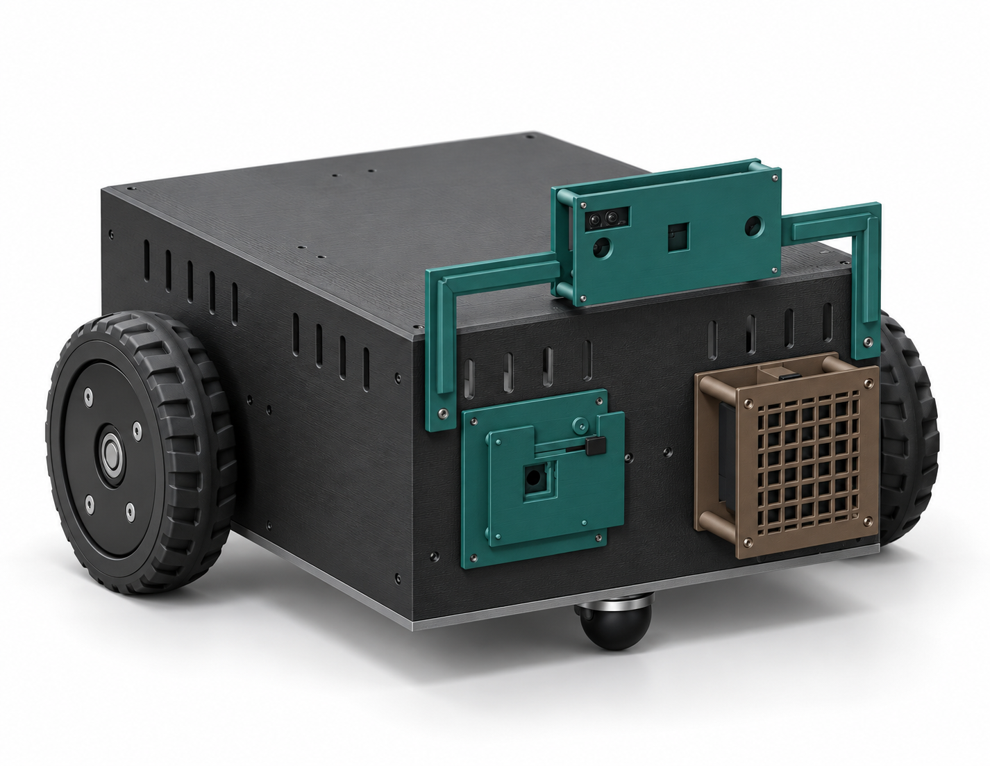
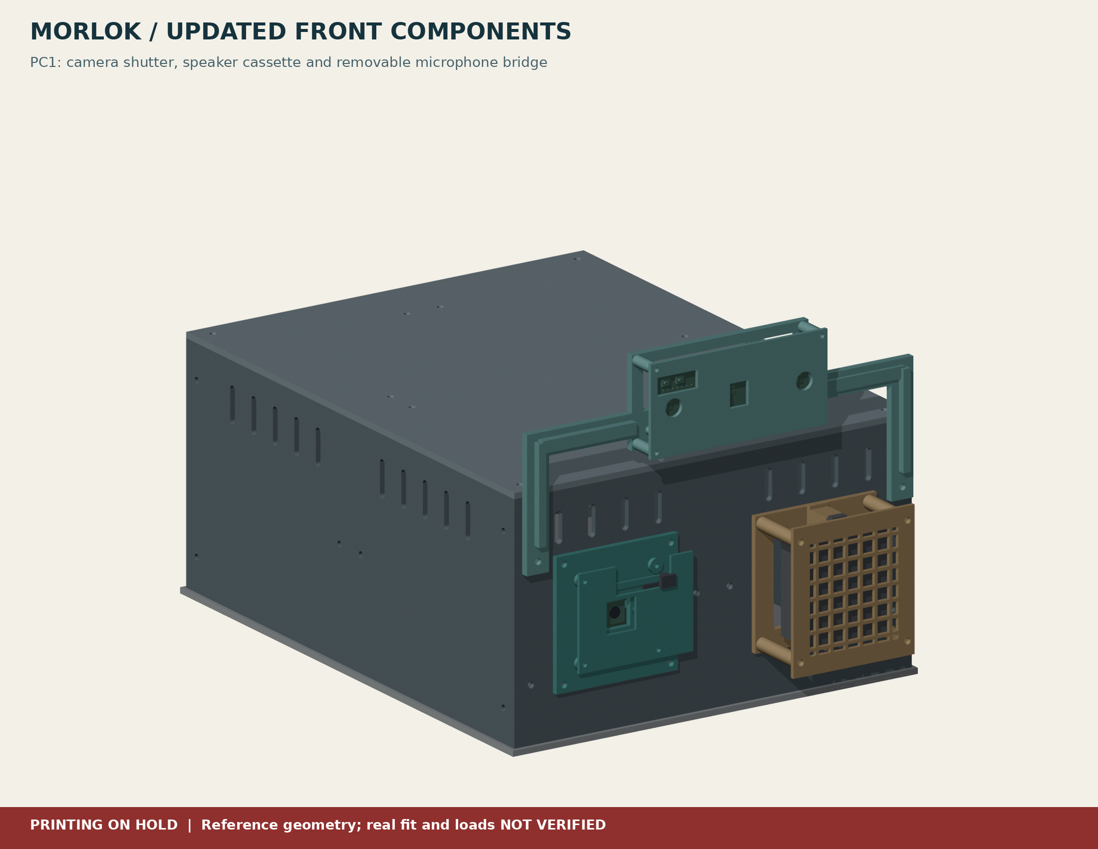
This is the updated design candidate the project requires: a Camera Module 3 Standard carrier with a captive sliding shutter, a front-mounted Seeed speaker cassette with a removable grille, and a removable top-front reSpeaker Lite bridge. These are actual editable CAD parts, not blank plates or component-envelope tokens.
The complete package was frozen with printing on hold. A selected C01/C02/C03 camera-shutter prototype is now undergoing a separate plate review; this is not a bulk-body or functional release. The updated candidate has digital checks, but the exact received devices, fasteners and functional clearances still need confirmation. Passing a mesh or collision check does not release physical fit, strength, acoustics, camera performance, privacy behavior, wiring or motor power.
What remains unchanged
The 24-piece R2 shell, its two 50 x 50 mm front openings, four 3.4 mm holes on each 58 x 58 mm module pattern, remain preserved. The separate metal deck remains only in this frozen PC1 reference package; later PF1 supersedes it for the current stationary build. New modules add parts. The camera is front-view left; speaker front-view right; microphones are above the service lid. The bridge is NOT a handle. Its added bending load has not been qualified on the existing shell/post fasteners.
Still unselected controls and indicators
Separate camera-capture/status indicators, a physical push-to-talk control and the independent drive-stop mount remain unselected interfaces. PC1 has no qualified LED, switch or stop-button cutouts. A removable future control-panel location may be studied in the uncut front-central region, approximately Y=-20..20 and Z=100..118 mm, above the module carriers; it spans a source seam and is only a planning reservation. Preserve vents, seam service and lid access. Do not assume every control fits there. The independent motor stop needs its own reachable, structurally qualified location and reviewed circuitry. No LED or switch diameter is invented.
What this package contains
Eleven individual STL types, matching STEP solids, editable CadQuery source, native Blender scenes, a manifest, quantities, source/assumption records, and scoped digital QA. Nine candidate types make thirteen installed candidate pieces; two further types are small local test sections. Reference electronics and the metal deck are explicitly not printable. No G-code, printer dispatch, purchases, wiring or energization occurred.
1. Geometry that actually supports the proposal
Camera Module 3 Standard
The official Standard mechanical drawing shows a 25 x 23.862 mm board, 1.12 mm PCB thickness, four 2.2 mm holes at x=2/23 and y=2/14.5 from the lower-left board datum, lens centre (12.5,14.4), and a 10.8 mm optical housing. The drawing reports 11.3 mm overall depth, while the product summary rounds the Standard body to 25 x 24 x 11.5 mm. These are reference dimensions, not a substitute for measuring the received camera. Wide is a different height and is not the selected candidate. [S1]
The carrier's converted camera-hole coordinates are u=+/-10.5, v=-12.4/+0.1 relative to the lens. The four source R2 module bolts remain u,v=+/-29. A 6 mm spacer length, 2.4 mm printed M2 clearances, 14 mm carrier optical opening and 16 mm retainer window are project choices requiring verification.
Seeed speaker 114993346
The manufacturer mechanical drawing resolves the features absent from TF1's body token: body width 44.6 +/-0.5, height 49.6 +/-0.5, total ear-to-ear height 65.5 +/-0.5, ear-hole pitch 57.5 +/-0.5, two 3.5 mm holes, total depth 22 +/-0.5, 7.0 +/-0.5 mm front-to-ear-front setback and 3.8 +/-0.3 mm ear thickness. Its rounded catalogue body is 50 x 45 x 22 mm. The 150 +/-10 mm lead and connector pitch do not define the actual connector body's clearance or cable bend. [S2]
PC1 uses the documented ear axes and deliberately keeps the entire speaker in front of the shell aperture. The visible reference model simplifies the ear outline; the hole axes, overall limits and depths are sourced. Cone excursion, compliant pads, acoustic seal, plug shape and actual tolerances remain unverified.
reSpeaker Lite: a real revision mismatch
Seeed's official wiki links ReSpeakerLitev1.1.step and states a nominal 86 x 35 mm board. The supplied STEP PCB instead measures approximately 82.024 x 34.007 x 1.51 mm. Total STEP component bounds are approximately 83.602 x 34.007 x 10.930 mm. We have not scaled one to match the other or invented four corner holes. [S3]
The STEP has two 2.2 mm PCB mounting holes, at source coordinates (42.73,-76.375) and (100.44,-105.295). Its microphone-package reference centres are approximately (45.725,-90.955) and (116.725,-90.955), on the underside. Package-sized front apertures avoid assuming an undocumented tiny acoustic-port location. The real USB-only 107990273 board revision, exact hole locations, microphone face and full populated height must be checked before a mounting print is released.
Datums and uncertainty
All geometry is in mm. Global +X is forward, +Y is the robot's left, +Z is up. Module coordinates (u,v,n) mean across, up, outward. Camera centre is global Y=-54,Z=59 at front plane X=138; speaker is Y=+54,Z=59. The bridge is based at X=140,Z=93, with two 2 mm spacers back to the source front panel. Supplier drawings/model supply reference geometry; running clearances, lattice, guards, spacer lengths and new accessory shape are project choices.
2. Camera carrier and physical shutter
Proposed construction, after the hold is lifted
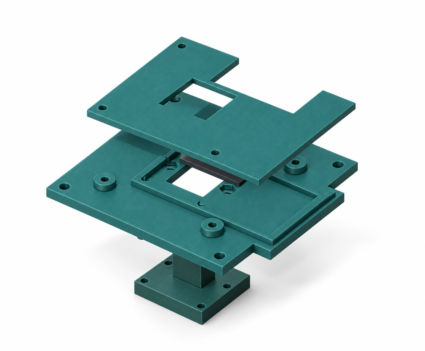
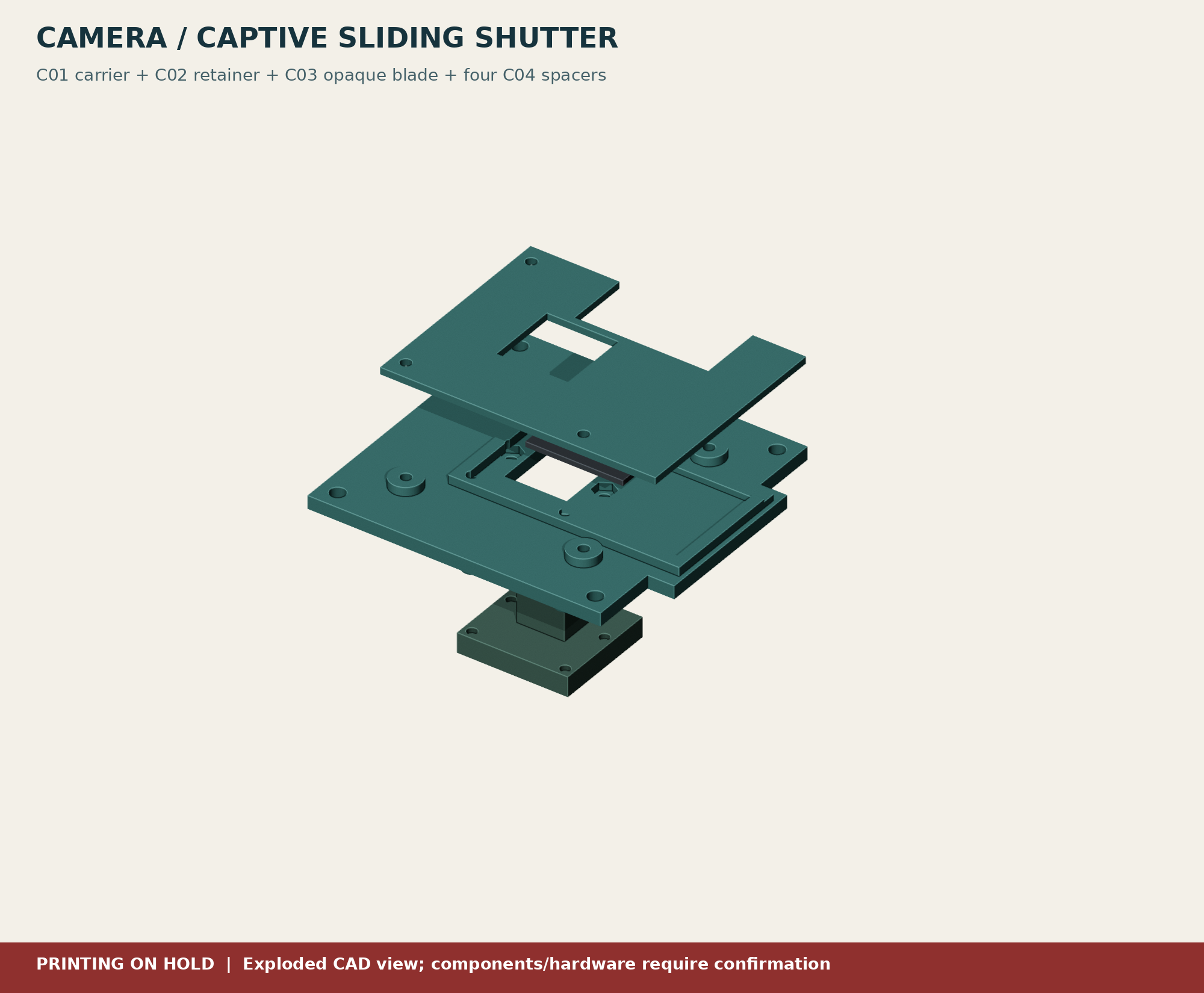
- Inspect the actual Standard camera and hardware. C01 has front-loading M2 hex-nut pockets, nominal 4.4 mm across flats and 1.8 mm deep. Measure nut dimensions, check seating and support loose nuts during assembly or service
- Position four C04 6 mm spacers between the PCB front mounting lands and the carrier rear. Fasten from the camera rear. No optical housing, component or flex cable may be clamped. Bolt tips must remain below the moving shutter's underside; no screw length is released
- Insert opaque blade C03 in the C01 guides, then attach separate retainer C02 with four M2 fasteners on project holes at (+/-20,+/-20). Those positions fall within the original 50 mm shell opening for rear nut access. Confirm actual nut/head clearance
- Attach the complete carrier with the existing four R2 module bolts. The original front panel is not drilled or stretched. The camera may be serviced by removing the carrier while supporting inside nuts
The blade has 24 mm travel. Its solid closed face covers the optical openings; the open position clears them. Nominal blade-to-base and blade-to-retainer running clearance is 0.4 mm on each side. The finger grip is above the retainer, and the end walls limit travel. This is a manual mechanism. Opening it must not trigger camera capture or cloud transmission.
Required camera checks
Verify actual spacer contact lands, bolt/nut stack, ribbon connector and relaxed cable/service loop. With the real camera, check autofocus motion and the full field of view in the open position at near and far focus, including vignetting at image corners. Check shutter retention and smooth full travel without binding or rubbing the lens. Test opaque material under the brightest intended lighting, with the camera actually capturing: nominal solid plastic is not proof of opacity. Confirm visible/tactile OPEN and CLOSED labels and fail-safe application behavior separately.
The digital continuous swept-volume check covers the printed blade and finger grip against the printed carrier/retainer through the entire 0-24 mm stroke. It excludes actual fasteners, camera flex, printing error, optical rays and physical opacity.
3. Speaker cassette and removable grille
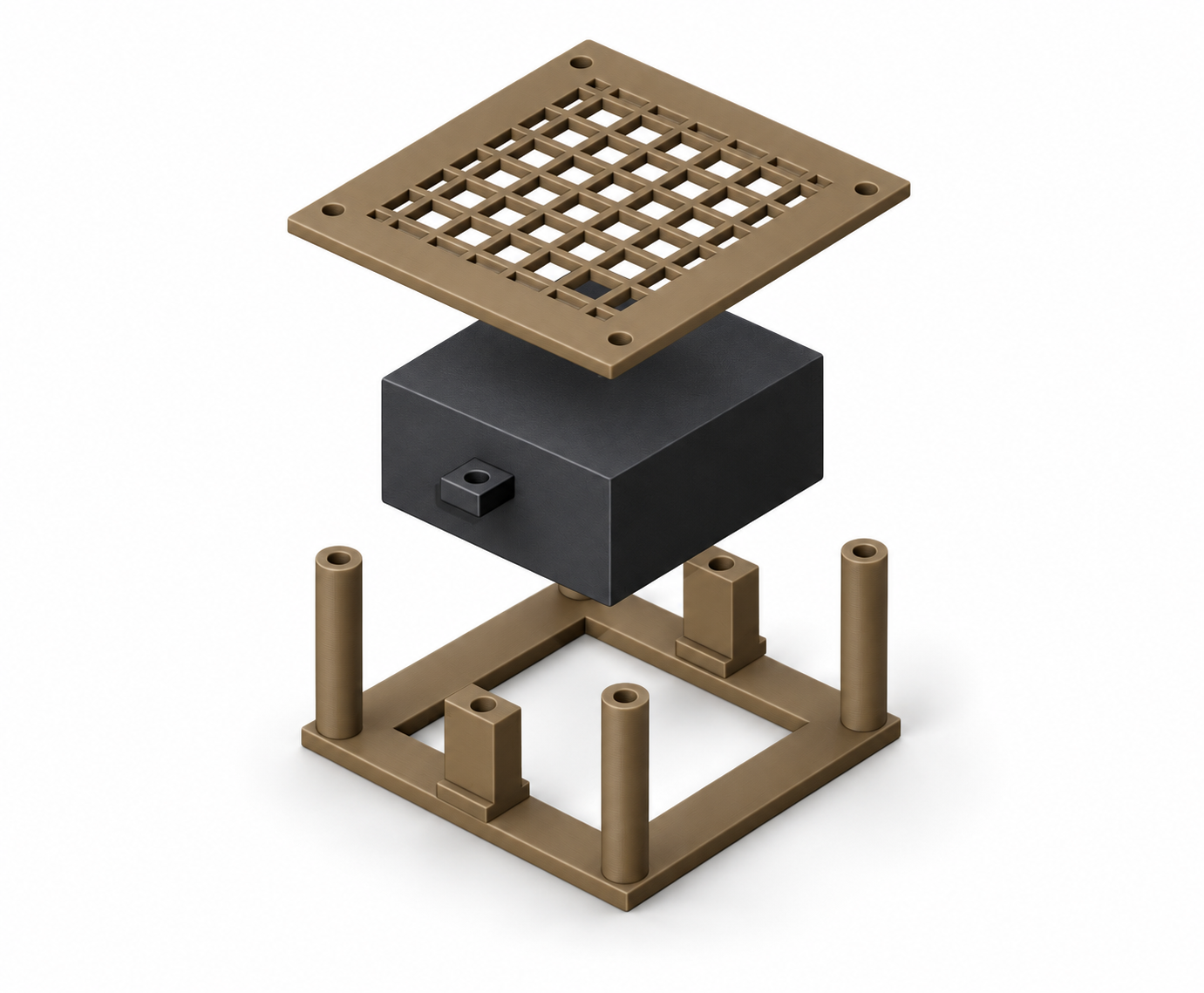
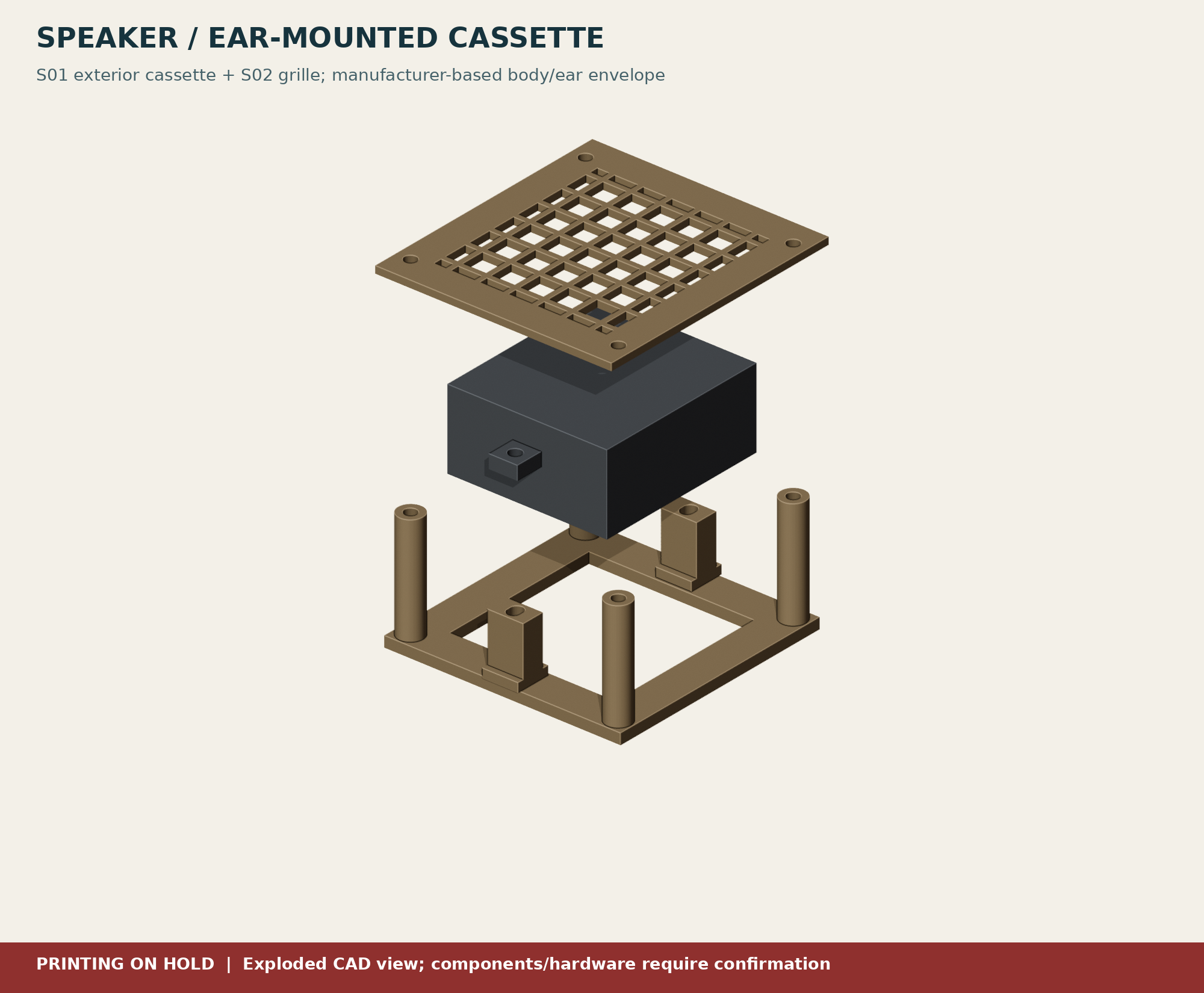
Proposed construction, after the hold is lifted
S01 supports the two real ear axes outside the source shell opening. Its nominal body rear is n=8, front n=30, ear back n=19.2 and ear front n=23 mm. S02's rear grille plane is n=33 mm, giving 3 mm nominal distance from the referenced body-front plane. The speaker's dynamic cone envelope is still unknown; 3 mm is not a qualified excursion clearance.
The ear fastener passages use 3.4 mm printed clearances with 1.2 mm slot travel along the ear pitch direction. Bolts enter from the rear before the cassette is installed. Rear head recesses are a project choice, 6.2 mm diameter with the same slot travel and 3.2 mm depth; the actual chosen heads must seat fully below the panel-contact face. The flared support feet stay below the conservative body envelope. The narrower upper supports preserve nominal body clearance.
Use measured washers/nuts at the ear fronts. Do not force an ear flat or torque plastic as metal. The four original R2 module axes also carry the grille columns. The proposed front-to-back stack through grille, column/carrier and 3 mm source panel is approximately 38 mm before head/washer/nut allowances. No final bolt lengths, torque or hardware order is released. Support inside nuts during removal.
The open centre gives a cable route through the existing shell opening. It does not locate the real speaker wire exit or guarantee connector passage. The lattice is a protective/acoustic candidate, not an acoustic result. A compliant pad or seal has not been sized; do not add one without checking its effect on stack, ear position and cone clearance.
Required speaker checks
Measure actual overall ears, hole pitch/diameters, ear setback/thickness and housing. Check fasteners through the supplied support section before a cassette batch. Verify the plug and cable route through the full service motion without tension, rubbing or pinching. With the real grille, establish cone-motion clearance, buzz/rattle, useful volume, feedback and microphone performance. Test at conservative levels first under a separately reviewed electronics procedure; this CAD guide authorizes no power test.
The digital check includes nominal reference geometry and a conservative combination of the drawing's stated body/ear-depth tolerances. It does not include real cone motion, wire, connector, gasket, chosen hardware or printer deviations.
4. Microphone bridge and USB privacy
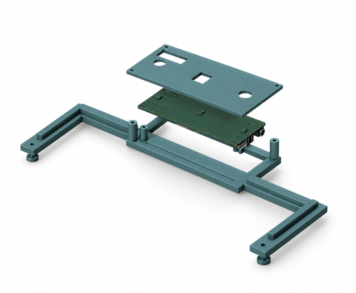
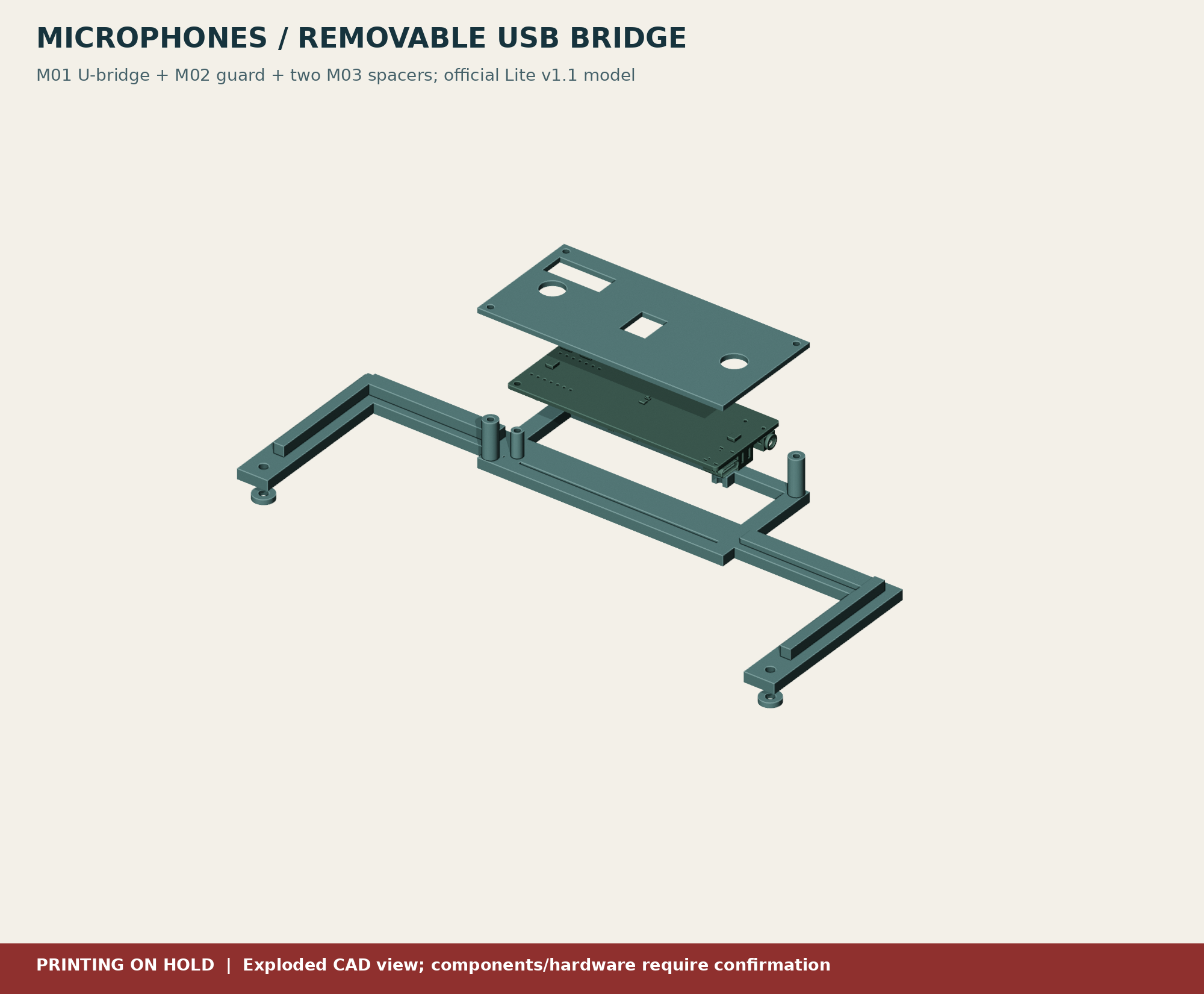
M01 is a separate 210 mm-wide U-bridge. Two M03 2 mm spacers place it forward of the preserved upper front shell/post fasteners at Y=+/-99,Z=93. M02 is a removable three-point guard. The source shell still has 24 pieces. Do not lift or carry MORLOK by this bridge; fastener bearing, loosening, panel bending, creep and drop/handling loads are NOT qualified.
The official Lite STEP is rigidly rotated so its microphone-bearing underside faces forward. Its component-rich side faces rearward. It is not a mirrored or scaled model. With source centre (81.25,-90.955), the transform is u=x-81.25, v=-y-23.955, n=15-z. The PCB fastener references become (-38.52,52.42) and (19.19,81.34). The board's 1.51 mm source thickness defines the provisional support height, not a measured production assembly.
The guard exposes both whole modeled microphone-package regions through 9 mm openings, the two-button area through a shared slot, and the central indicator region through a window. Those openings must be checked against the actual board orientation and actual acoustic inlet positions. Do not reverse the board to make a connector more convenient. Assess microphone path, housing resonance, fan noise and speaker vibration with actual hardware.
USB disconnect and service
The USB edge remains open. A deliberately unoccupied, assumed insertion/extraction corridor is checked in CAD, extending from the modeled Type-C mouth. It is an allowance, not a model of the actual plug or hand. Verify actual plug insertion/removal, grip access, bend radius, strain relief and unplugging without pulling the PCB or breaking the bridge.
For the selected USB-only Lite configuration, physically unplugging its sole USB link is the baseline audio-off action. There must be no auxiliary power, XIAO/radio or alternative data path. The built-in mute control is not claimed as hardware isolation. No new mic-only switch is invented. Label the externally reachable disconnect clearly; verify the real path before relying on it.
The model has 2 mm nominal clearance ahead of the full service-lid lift envelope. Real part warp, fastener heads, cables and hand/tool access are excluded. Physically verify lid removal/replacement with the bridge installed and verify that the bridge itself can be detached without stressing wires. Its stiffness and the added bending load on the source fasteners remain explicit release gates.
5. Candidate parts and quantities
ALL PRINTING REMAINS ON HOLD. Quantities below are a design inventory, not an instruction to start a batch.
| Part | Candidate assembly qty | Approx. print bounds, mm | Purpose |
|---|---|---|---|
| C01 camera carrier | 1 | 72 x 66 x 5 | R2 interface, optical relief and shutter guides |
| C02 shutter retainer | 1 | 62 x 48 x 1.6 | Removable front cover |
| C03 opaque slider | 1 | 22 x 27.5 x 5.9 | Solid blade and exposed grip |
| C04 6 mm spacer | 4 | diameter 4.2 x 6 | Camera PCB-front spacing |
| S01 speaker cassette | 1 | 66 x 67.5 x 33 | Ear supports and grille columns |
| S02 speaker grille | 1 | 66 x 72 x 2 | Removable lattice face |
| M01 U-bridge | 1 | 210 x 96 x 18 | Separate microphone support |
| M02 microphone guard | 1 | 96 x 46 x 2 | Mic, buttons and indicator access |
| M03 bridge spacer | 2 | diameter 8 x 2 | Nominal 2 mm lid-front gap |
| TOTAL CANDIDATE PIECES | 13 | 9 unique types | Added to the 24-piece shell |
| T01 guide section | 1 optional test | 26 x 32 x 5 | Small source-derived shutter channel |
| T02 ear support section | 1 optional test | 16 x 10.75 x 19.2 | One ear/head-recess section |
If every future candidate were qualified, 24 shell pieces plus 13 candidate pieces would mean 37 installed printed pieces, excluding other internal mounts. T01/T02 and TF1 coupons/dummies are not installed pieces. Earlier R2 camera/LED plates are alternatives; do not stack them behind the new camera/speaker modules.
Printing review, only after explicit release of the hold
All eleven meshes fit the Creator 5 Pro's official 256 mm cube, including an 8 mm XY brim allowance. The 210 mm bridge fits the AD5X's 220 mm nominal bed, but an 8 mm brim around it does not. Use the exact machine profile and examine the full layer preview. All STL files are normalized to Z=0 and are unitless: import in mm at 100% scale.
Broad backs/blades/grilles lie on the bed; posts and columns grow upward. Use the intended eventual material for dimensional tests. A 0.4 mm nozzle and 0.20 mm layers are untested starting choices, not a released profile. Opaque shutter stock and actual optical blocking must be verified. Begin with a coupon and the relevant local section after review; do not infer that either small section qualifies the whole module.
Candidate hardware inventory, not a purchase list: 4 M3 camera module bolts, 4 M2 camera-board bolts/nuts, 4 M2 retainer bolts/nuts; 4 long M3 speaker module/grille bolts, 2 M3 speaker ear bolts/nuts; 2 replacement-length M3 bridge/shell bolts, 2 M2 board bolts/nuts and 3 M2 guard bolts/nuts. Appropriate measured washers and lock/retention details remain to be selected. Reuse source nuts only if inspection and actual engagement permit. No length or torque is released.
Count replacements correctly: the eight camera/speaker module bolts replace the earlier eight carrier bolts. The two longer bridge bolts replace two existing shell/post bolts. They do not add ten positions to the historical 48 M3 positions. Two speaker-ear bolts are additional, giving 50 candidate M3 positions if the whole historical shell-plus-carriers baseline is retained. Thirteen M2 board/retainer/guard positions are additional candidate demand. Check usable stock, exact lengths, washers and retention; shopping pack quantities remain TBD.
6. Checks, limits and next decisions
Digital evidence supplied
- Eleven exported meshes: closed edges, consistent winding, single connected component, positive volume, no degenerate triangles and bed-normalized Z=0
- Valid single-solid CAD for each printed type; Creator 5 Pro envelope/brim checks
- Continuous 0-24 mm shutter swept-volume check against its printed carrier and retainer
- Camera/speaker reference-envelope checks; a conservative speaker body tolerance envelope; Lite official STEP against bridge and guard
- Cross-module/source-front-panel placement, a nominal 85 mm service-lid lift envelope and an assumed USB insertion/extraction corridor
- Preserved 24 shell meshes in the native assembly scene; untouched source geometry and source hashes
These are scoped geometry checks. They exclude real fasteners, cables, printing variation, loads, optical rays, acoustic performance, cone movement, electrical behavior and actual received revisions. Where simplified references are used, the preview says so. A zero intersection volume does not prove a functional assembly.
Gates before any mounting release
- Confirm exact camera Standard variant, speaker 114993346 and USB-only Lite 107990273. Resolve the explicit Lite STEP/wiki/received-board mismatch
- Measure actual board holes, PCB lands/heights, ear geometry, all plugs/cable bends and the real hardware stack; revise only the affected candidate source
- Review proposed test-print scope and explicitly lift the printing hold for those pieces. Retain original failed prints/measurements and all prior revisions
- Check fit without force, actual screw engagement, nut capture/access, sharp protrusions and service disassembly; verify bridge stiffness, bending/retention and source panel/post loading
- Verify camera field of view and autofocus, closed-shutter opacity/retention, actual microphone acoustic path/orientation, USB insertion/extraction/disconnect path and lid removal
- Only under later reviewed procedures, qualify stationary camera/audio, privacy, thermal/acoustic performance and complete closed-body integration. Traction/mobility remains separately gated
Use measurement_gate_record.csv. Every physical test starts NOT RUN. No test result has been fabricated.
Editing and provenance
cad/build_candidates.py is the editable geometric source; step contains editable solid exports. parameters.json records evaluated design/reference values and is not an automatic configuration loader. Changing dimensions requires editing the source, regenerating exports and rerunning all affected checks. stl_PRINTING_ON_HOLD contains individual print candidates only. assembly_meshes and reference_models are preview/reference inputs, not whole-assembly prints. The native Blender file is an editable mesh scene, not the parametric CAD authority.
TF1 and original R1/R2 files are unchanged. Source PDFs were visually inspected; source URLs and downloaded-source SHA-256 values are recorded in sources_and_assumptions.json. The official Lite STEP is retained for reproducible validation. Do not substitute a different file or board revision silently.
[S1] Raspberry Pi Camera Module 3 Standard mechanical drawing: https://datasheets.raspberrypi.com/camera/camera-module-3-standard-mechanical-drawing.pdf ; product summary: https://www.raspberrypi.com/products/camera-module-3/
[S2] Seeed 114993346 manufacturer datasheet hosted by DigiKey, mechanical image on page 4: https://mm.digikey.com/Volume0/opasdata/d220001/medias/docus/8932/114993346.pdf
[S3] Seeed Lite official wiki: https://wiki.seeedstudio.com/reSpeaker_usb_v3/ ; its official v1.1 STEP: https://files.seeedstudio.com/wiki/respeakerv3/ReSpeakerLitev1.1.step
[S4] Original R1/R2 source map: private Robot Space source archive
[S5] Creator 5 Pro specification: https://www.flashforge.com/products/flashforge-creator-5-pro ; AD5X: https://www.flashforge.com/products/flashforge-ad5x-3d-printer
First complete shutter fit prototype
The selected limited prototype uses C01 camera carrier, C02 retainer and C03 slider, one each. T01 removes the retainer bosses and is not a substitute for the full captive mechanism. No camera, C04 spacers or source shell panel are needed for this bench trial. The frozen package’s HOLD labels remain as revision history; the selected prototype has a separate review.
Import the supplied STL parts as separate objects in millimetres at 100 percent scale, then arrange them apart. Their local XY origins otherwise overlap. Keep C01’s flat back down with rails upward, C02 flat down, and C03’s blade down with grip upward. With 20 mm gaps, the row is 196 x 66 mm; an 8 mm outer brim allowance is 212 x 82 mm. Check the actual printer’s full usable plate and layer preview.
C03 is not entirely support-free. Its finger tab cantilevers 4.1 mm beyond the blade and its upper grip has 2 mm side lips. Review local support under that tab/grip while keeping the sliding/contact faces unscarred. Do not place trapped supports in the assembled channel. For a physically confirmed 0.4 mm nozzle, 0.20 mm layers, three walls and four top/bottom layers are starting review choices; the exact machine and PLA profile govern temperatures and speed.
Four measured-length M2 through-bolts and four nuts assemble the 6.6 mm nominal plastic stack. Check actual nuts, washers and head fit; do not use self-tappers or bow the thin retainer. Inspect cooled flatness, elephant foot, burrs and full free 24 mm travel. Black PLA is a dimensional prototype material here, not proven optical blocking, PETG qualification or load-bearing approval. No completed physical fit result is established.